Power feedback power factor correction high frequency inverter

a high-frequency inverter and power factor technology, applied in the direction of electric variable regulation, process and machine control, instruments, etc., can solve the problems of low efficiency, waste of power, and increase power consumption

Inactive Publication Date: 2006-04-04
CHIOU YIH FANG
View PDF1 Cites 2 Cited by
  • Summary
  • Abstract
  • Description
  • Claims
  • Application Information

AI Technical Summary

Problems solved by technology

Therefore, the known circuit produces a large ripple current and, consequently, leads to low efficiency.
This phenomenon apparently leads to the result of increasing power consumption and the waste of power.

Method used


Image

  • Power feedback power factor correction high frequency inverter
  • Power feedback power factor correction high frequency inverter
  • Power feedback power factor correction high frequency inverter

Examples


Embodiment Construction

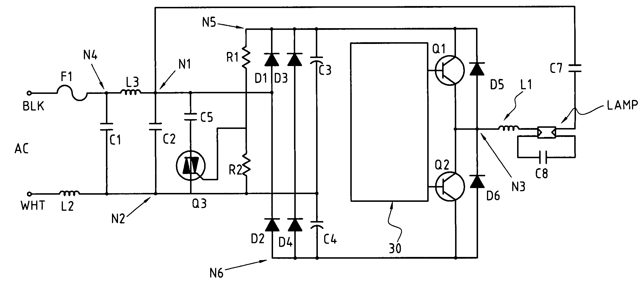
[0014]With reference to the drawings and in particular to FIG. 3, a fluorescent lamp LAMP is energized by a high frequency half-bridge inverter formed by two transistors Q1 and Q2. A choke L1 is connected in series with the lamp. A tuning capacitor C8 is connected in parallel with the lamp. A coupling capacitor C7 is connected from the lamp to the junction N1.

[0015]The source of power for the ballast is an input AC, typically from a 120V, 60 Hz mains (line). The input line is connected to a double rectifier D1-D2-C3-C4 through a fuse F1, an interference filter formed by line choke L2 and a capacitor C1, and the power factor correction circuit formed by isolating inductor L3 and tuning capacitor C2. The negative output of double rectifier is connected to circuit ground, and the positive output is the high voltage supply for the inverter.

[0016]The inductor L3, the tuning capacitor C2, the diodes D1 and D2, and the coupling from the tuned high frequency circuit, act together to provide...


PUM


Abstract

An electronic high frequency supply, such as lamp ballast, includes a double rectifier, two storage Capacitors in series, and an isolating inductor between rectifier and an AC input. Each storage capacitor is charged to a voltage greater than peak of the AC input. An inverter is connected to the storage capacitors, and has a high frequency inductive load circuit connected between inverter output and a junction between the isolating inductor and double rectifier. A capacitor, connected from the junction to the junction of two storage capacitors, forms a high frequency resonance circuit with the inductive load circuit. Current is drawn from the input AC only as a series of pulses at the inverter frequency. The isolating inductor filters out the high frequency part of the current pulse and makes the input current near sine wave.

Description

BACKGROUND OF THE INVENTION[0001]1. Field of the Invention[0002]The present invention relates to power feedback power factor correction high frequency inverters, and more particularly to the power feedback power factor correction high frequency inverter used for a lamp ballast.[0003]2. The Prior Arts[0004]Electronic lamp ballasts currently available on market have a circuit as shown in FIG. 1, which comprises an AC (alternate current) filter circuit 10, a bridge rectifier circuit 11, a DC (direct current) rectifier circuit 12 and a DC / AC conversion circuit 13. The electronic lamp ballast drives a lamp tube 14 to start irradiating. However, the DC rectifier circuit 12 of the known electronic ballast uses only a single capacitor 20 to form the filter circuit. Although it has the advantages of low cost, simple circuit, and high load variation resistance, yet this type of filter circuit has a shorter period of charging current which occurs only when the voltage at the power source side ...

Claims


Application Information

Patent Timeline
Patent Type & Authority Patents(United States)
IPC IPC(8): G05F1/00H05B37/02H02M1/00H02M1/42H05B41/28H05B41/282
CPCH02M1/425H05B41/28H05B41/282Y02B70/126Y02B20/183Y02B20/00Y02B70/10
Inventor CHAO, JAMES CHIEN FANZHANG, KANGHONGCHIOU, YIH-FANG
Owner CHIOU YIH FANG
Why Eureka
Try Eureka