Method and apparatus for detecting welding of a relay contact

a relay contact and relay technology, applied in the direction of motor/generator/converter stopper, dynamo-electric converter control, instruments, etc., can solve the problems of inability to determine the welding of the relay contact, and inability to detect welding

Active Publication Date: 2006-01-26
SUBARU CORP +1
View PDF2 Cites 57 Cited by
  • Summary
  • Abstract
  • Description
  • Claims
  • Application Information

AI Technical Summary

Benefits of technology

[0018] For the sequence control used in the present invention, a various kinds of the sequence controls can be considered. However, considering that it is desirable that the number of steps to be taken is small; that the welding of the contact of the first main relay and the second main relay can be independently and securely detected; and that it can be guaranteed that the contact of each of the relays is in the suspension state when it is determined that the contact is in a normal state, it is preferable that the sequence control comprises: the first step for controlling the first main relay to be off; the second step for controlling the precharge relay to be on after the first step; the third step for controlling the second main relay to be off after the second step; and the fourth step for controlling the precharge relay to be off after the third step and

Problems solved by technology

However, if the precharge relay is provided, still it is possible that the welding of the contact of the main relay occurs.
However, with this method, it cannot be determined that the welding occurs unless the welding occurs at the contacts of both main relays and also it cannot be detected that the welding occurs at only one of either of the main relays.
However, in this method, it is necessary to provide the main relay with a special mechanism for detecting the state of the movable part thereof; and therefore this method lacks in versatility and also it is necessary to suf

Method used


Image

  • Method and apparatus for detecting welding of a relay contact
  • Method and apparatus for detecting welding of a relay contact
  • Method and apparatus for detecting welding of a relay contact

Examples


Embodiment Construction

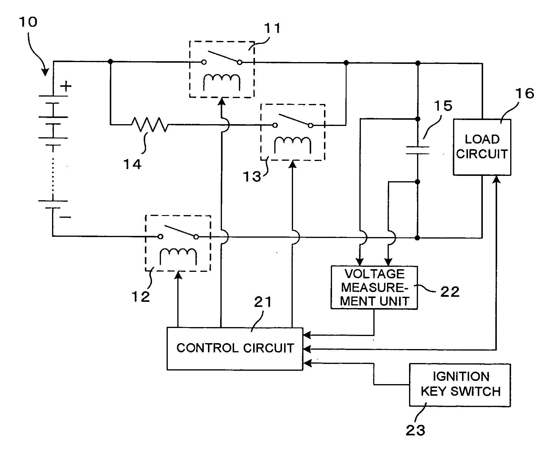
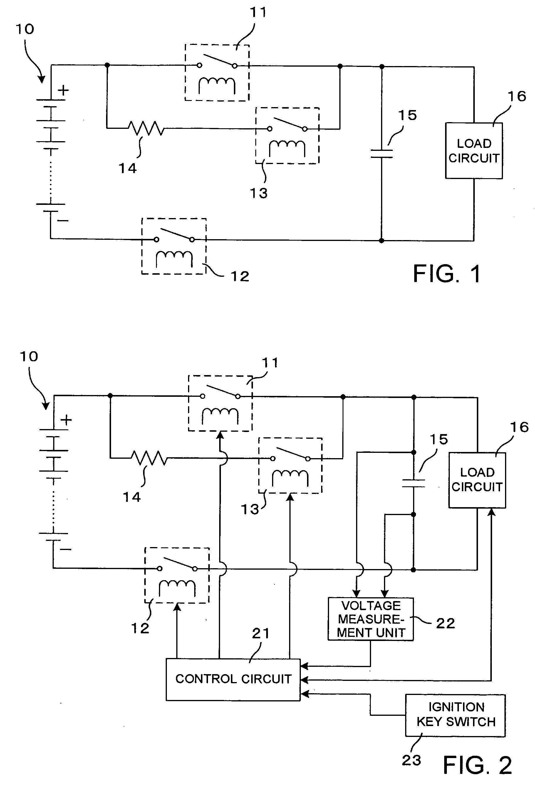
[0023]FIG. 2 is a view showing one example of a circuit to which a detection method according to the present invention applies. The circuit is intended for application to an electric automobile or a hybrid electric automobile, and has the same configuration as the circuit as shown in FIG. 1. However, FIG. 2 differs from FIG. 1 in the points such that control circuit 21 for controlling load circuit 16 and for performing an ON / OFF control of first main relay 11, second main relay 12 and precharge relay 13; voltage measuring unit 22 for measuring and outputting to control circuit 21 the voltage across both ends of capacitor 15, that is, the voltage across both ends of load circuit 16; and ignition key switch 23 interlocked with an ignition key in the electric automobile or the hybrid electric automobile are clearly shown. Load circuit 16 is, typically, an inverter circuit. Since this circuit is a circuit for the electric automobile or the hybrid automobile, control circuit 21 itself do...


PUM


Abstract

A method for detecting a welding of a relay contact in a circuit having a DC power supply; a load circuit; a first main relay and a second main relay respectively inserted in a pair of power supply lines disposed between the DC power supply and the load circuit; and a precharge relay which is provided in parallel to the contact of the first main relay has the step of carrying out a sequence control to each of the relays (11, 12, 13) while measuring voltage across both ends of the load circuit (16) when shifting from a normal operation state in which a first main relay (11) and a second main relay (12) are controlled to be on and the precharge relay (13) is controlled to be off to a suspension state in which each of the relays (11, 12, 13) are controlled to be off. The welding of the relay contact of the first main relay (11) and the second main relay (12) is determined independently and separately from a correspondence between the proceeding of the sequence and the measured voltage.

Description

TECHNICAL FIELD [0001] The present invention relates to a system having a DC (direct current) power supply such as a secondary battery, and a load circuit, for example an inverter circuit, or the like which is driven by the DC power supply. More particularly, the present invention relates to a method and an apparatus for detecting, in such a system, welding of relay contacts each of which is inserted in a pair of power supply lines between the DC power supply and the load circuit. BACKGROUND ART [0002] A hybrid electric automobile, an electric automobile, and the like have a constitution in which a motor is driven by an electric power from a DC power supply such as a secondary battery. In this case, the constitution in which a DC motor is directly driven by the electric power from the DC power supply is rarely employed. Instead, the electric power from the DC power supply is supplied to an inverter, and an AC (alternate current) power or a DC power to be supplied to the motor is gen...

Claims


Application Information

Patent Timeline
IPC IPC(8): H02P1/00H01H47/00
CPCY10T477/30H01H47/002H02H9/001G01R31/3278H01H47/00
Inventor TEZUKA, KAZUNARI
Owner SUBARU CORP
Why Eureka
Try Eureka