Efficient power system

a power system and energy saving technology, applied in the direction of greenhouse gas reduction, transportation and packaging, ac network load balancing, etc., can solve the problems of increasing power generation capacity, large capital expense required when increasing capacity, and difficulty in locating a new power plan

Inactive Publication Date: 2007-06-28
COGENERATION ENERGY CORP
View PDF2 Cites 58 Cited by
  • Summary
  • Abstract
  • Description
  • Claims
  • Application Information

AI Technical Summary

Problems solved by technology

However, increasing power generation capacity is problematic.
Large capital expense is required when increasing capacity.
In addition, siting of a new power plant is difficult due to both environmental factors and the frequent opposition of communities near a proposed site.
New power plants, once constructed, may produce undesirable byproducts such as greenhouse gases, coal ash or nuclear waste.
Use of additional energy in many cases increases reliance on fossil fuel, which is increasing in price and decreasing in reliability of supply.
Even when additional power is available, its use entails increased cost for domestic and industrial customers.
However, the prior art does not provide for continuous and relatively complete use of power supplied from a utility.
While this system interfaces power from renewable sources, no provision is made for processing voltage from a utility line for improving efficiency.
These prior art schemes do not examine an energy input waveform for portions of input power to determine whether input power may be regarded as excess power.
They also do not provide load dependent response or response to battery level to determine a charging cycle.

Method used


Image

  • Efficient power system
  • Efficient power system
  • Efficient power system

Examples


Embodiment Construction

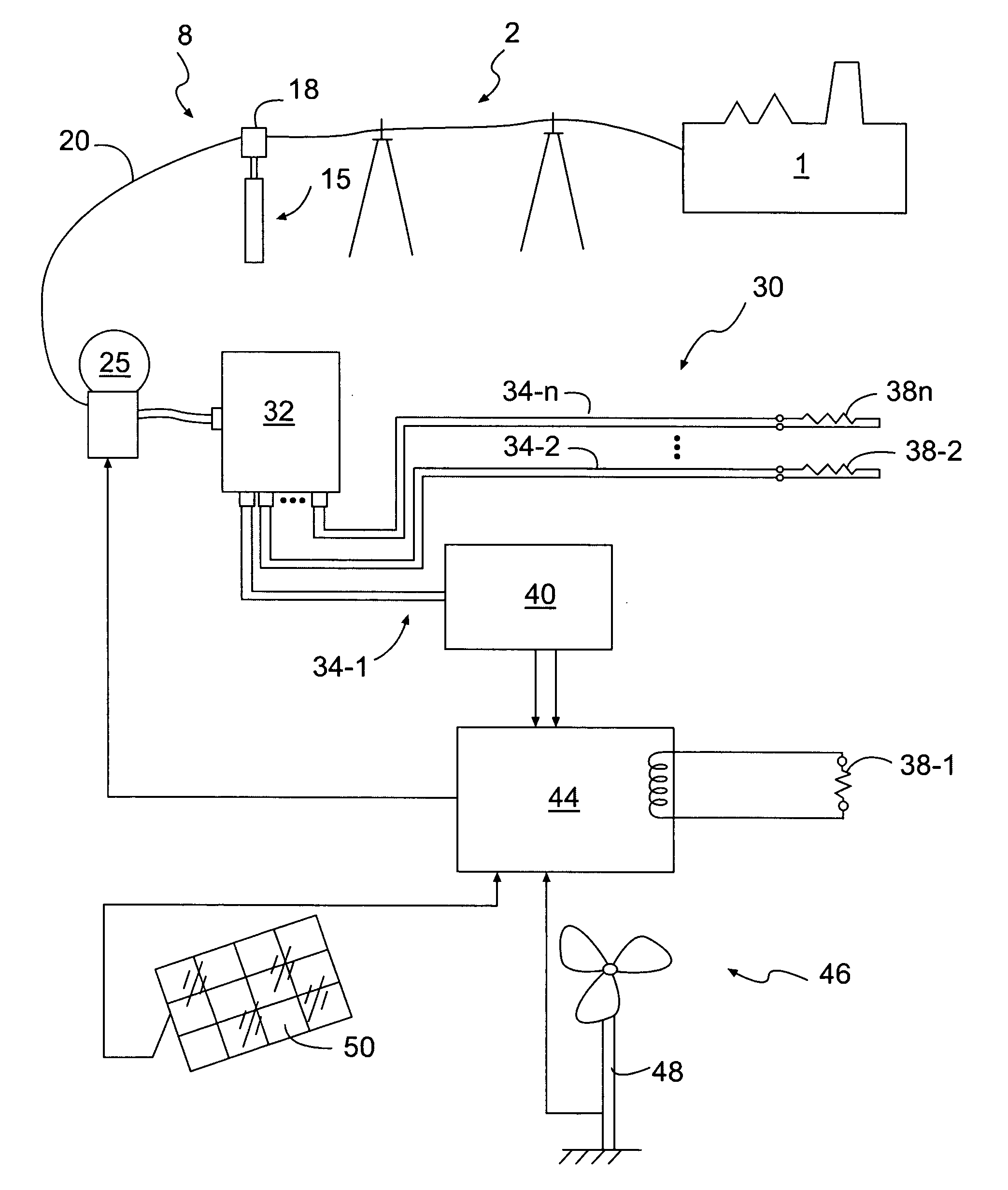
[0026]Embodiments of the present invention include a system and method for efficient use of power supplied from a utility to a load or loads in a facility. A utility will commonly comprise a commercial power company franchised to supply electricity. However, a utility will also include a source customarily comprising a main source of power for a facility. A facility may include a home, office or industrial building, or may include a combination of buildings.

[0027]Utilities provide power at a voltage approximating a rated line voltage. Each nation specifies a rating for line voltage. For example, in the United States, alternating current rated line voltage is 110 volts. Commonly, utilities may supply 105-120 volts to utility lines rated at 110 volts. Appliances and other items designed for use in the United States will operate satisfactorily when supplied at a nominal voltage level, 107 volts, for example. Therefore, the energy embodied in a portion of a power input sine wave above 1...


PUM


Abstract

A power system and method make highly efficient use of power supplied from a utility to a facility. A 110-volt line will commonly supply between 107 to 120 volts. A power system couples energy from the utility to a load circuit and may interface with further sources to supply the load circuit. The power system limits output voltage circuit to a preselected nominal level, e.g., 107 volts. Energy provided by the utility which is embodied in voltage above the nominal level is diverted to a charging circuit to charge a storage circuit. On command, the storage circuit delivers input power coupled to a waveform generator which produces a mirror of the waveform of the utility voltage as a supplemental AC voltage. The supplemental voltage is provided to the facility circuit either in response to a user-generated control signal, an output level from the storage circuit or in response to load requirements.

Description

FIELD OF THE INVENTION[0001]The present subject matter relates to efficient utilization of alternating current electrical power, and also using stored energy to reduce alternating current demand from a utility.BACKGROUND OF THE INVENTION[0002]Energy conservation has long been a desirable objective. At the present time, many factors make energy conservation an extremely important objective. Many major metropolitan areas suffer “blackouts” or “brownouts” at times of peak demand. However, increasing power generation capacity is problematic. Large capital expense is required when increasing capacity. In addition, siting of a new power plant is difficult due to both environmental factors and the frequent opposition of communities near a proposed site. New power plants, once constructed, may produce undesirable byproducts such as greenhouse gases, coal ash or nuclear waste. Use of additional energy in many cases increases reliance on fossil fuel, which is increasing in price and decreasin...

Claims


Application Information

Patent Timeline
Patent Type & Authority Applications(United States)
IPC IPC(8): H02J7/00
CPCH02J3/32Y02E70/30H02J3/383H02J3/386H02J3/382Y02E10/566Y02E10/763H02J3/38Y02E10/563H02J2300/40H02J2300/28H02J2300/20H02J2300/24H02J3/381Y02E10/56Y02E10/76H02J3/46
Inventor ARCENA, ANTONIO D.
Owner COGENERATION ENERGY CORP
Why Eureka
Try Eureka