DC/DC converter with LLC serial resonance

A technology of converters and series capacitors, applied in the direction of converting DC power input to DC power output, instruments, adjusting electrical variables, etc., can solve problems such as limited input voltage and small range

Inactive Publication Date: 2002-09-11
DELTA ELECTRONICS INC
View PDF0 Cites 60 Cited by
  • Summary
  • Abstract
  • Description
  • Claims
  • Application Information

AI Technical Summary

Problems solved by technology

However, the LCC resonant converter is stil

Method used


Image

  • DC/DC converter with LLC serial resonance
  • DC/DC converter with LLC serial resonance
  • DC/DC converter with LLC serial resonance

Examples


Embodiment Construction

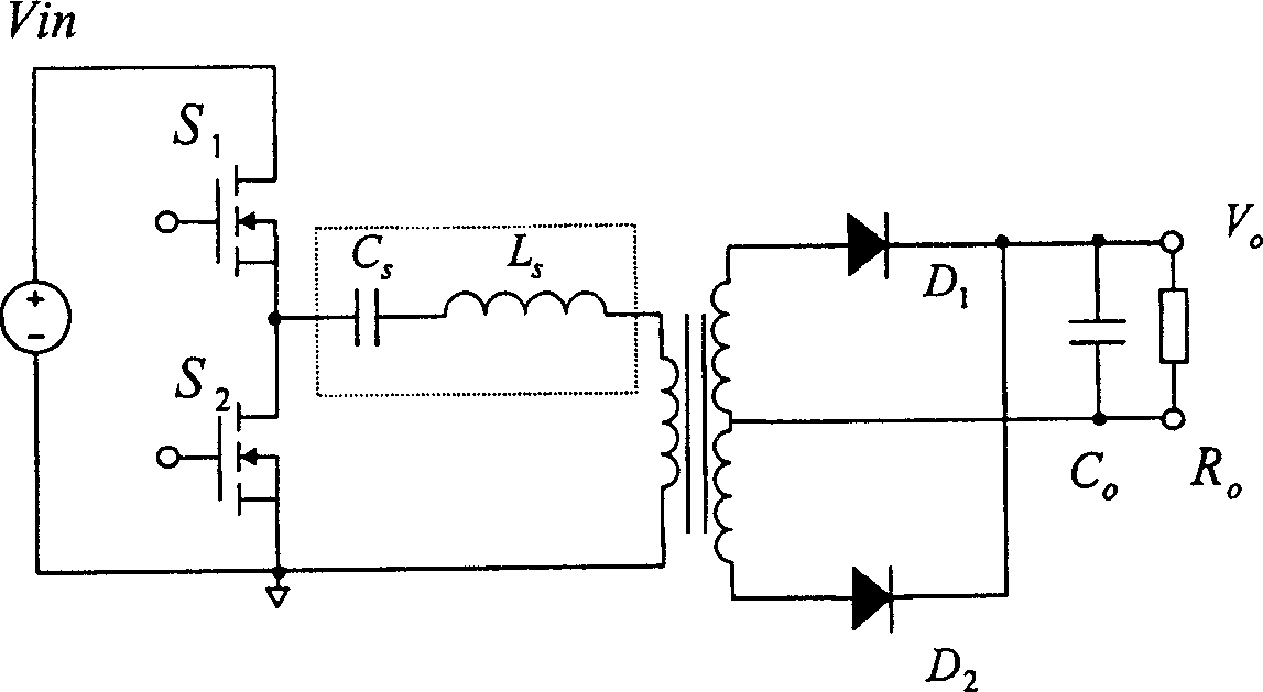
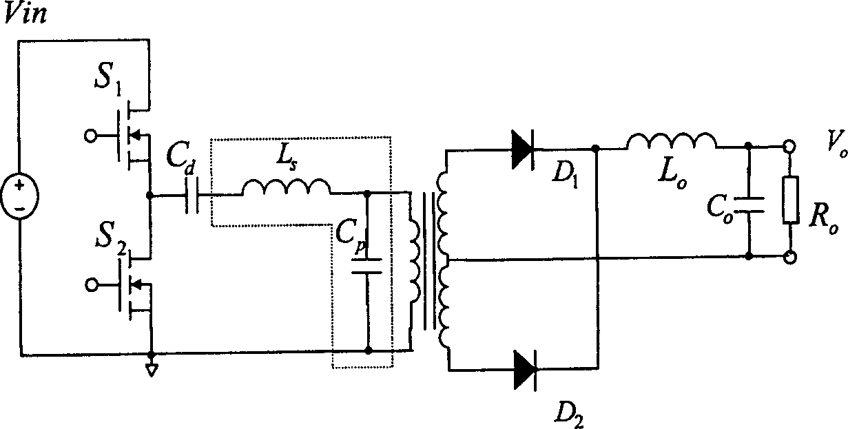
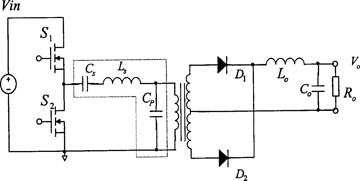
[0022] Figure 4 A schematic circuit diagram of the LLC series resonant DC / DC converter of the present invention is shown. The novel resonant converter includes a square wave generator 110 , an LLC resonant network 120 , a high frequency transformer 130 , a rectifier circuit 140 and an output filter 150 . The square wave generator circuit 110 is a half bridge inverter and contains two switches (S1 and S2). Instead of a half-bridge inverter, it is also possible to use a full-bridge inverter instead of the half-bridge circuit. The LLC resonant network 120 is connected across two terminals of the second switch S2 (ie, terminals A and B) to receive a square wave signal when the switches S1 and S2 are turned on and off alternately. The LLC resonant tank 120 contains a series capacitor C s connected in series with a series inductor L s . The LLC resonant tank 120 also includes a shunt inductor L m And connected to the primary side winding of the transformer 130. The series ca...


PUM


Abstract

The invention discloses a DC/DC converter. The DC/DC converter includes a square wave generator, which is used to output a series of voltage in form of square wave. The said square wave generator includes a serial capacitor which is connected to serial inductor and parallel inductor. Primary side of transformer is cascaded to a serial inductor in the DC/DC converter, then connected to an inductorin parallel. Secondary side of transformer is connected to a rectification circuit so as to provide a rectified DC voltage for output load circuit. The first characteristic resonance frequency of theserial capacitor and the serial inductor are expressed as fs. The second characteristic resonance frequency of the serial capacitor and the serial inductor as well as parallel inductor are expressed as fn where fs>fn. Switching of variable frequency in the converter carries out the output adjustment. Based on frequency switching between first and second characteristic resonance frequency, the converter realizes high conversion efficiency when working under high input voltage.

Description

technical field [0001] The present invention relates generally to power supply systems involving DC / DC conversion operations. More particularly, the present invention relates to an improved circuit design and construction for better power conversion efficiency, wider operating range and improved soft switching performance. Background technique [0002] The design and manufacture of known art DC / DC converters have limitations of low power conversion efficiency and narrow operating range. Specifically, in known Pulse Width Modulation (PWM) converters, in order to maintain the output voltage in an environment of falling input voltage and for the required hold-up time, a compromise must be made on the duty cycle and other operating parameters to The hold-up time requirement is met under a low input voltage condition. Power conversion efficiency is sacrificed for normal operation with an input voltage within its normal range. Such inability to optimize the circuit design to se...

Claims


Application Information

Patent Timeline
IPC IPC(8): H02M3/337
CPCH02M3/3382Y02B70/10H02M3/33573H02M3/33571H02M3/01
Inventor 黄贵松章进法顾亦磊
Owner DELTA ELECTRONICS INC
Why Eureka
Try Eureka