Adjustable resonant buck converter

a buck converter and buck converter technology, applied in the direction of electric variable regulation, process and machine control, instruments, etc., can solve the problems of large space constraints, high power loss of silicon-controlled full-bridge rectifiers, and high current ripples, and achieve low power loss, low ripple current, and compactness.

Active Publication Date: 2013-02-21
MKS INSTR INC
View PDF4 Cites 57 Cited by
  • Summary
  • Abstract
  • Description
  • Claims
  • Application Information

AI Technical Summary

Benefits of technology

[0003]The invention features a resonant buck converter circuit that is more compact in comparison to a standard buck converter, and includes low power loss and low ripple currents. Because the resonant buck converter of the present invention is based on a resonant topology, the switching loss is negligible. In addition, because the resonant converter can be operated at high switching frequencies, the converter advantageously does not require large components.
[0004]Furthermore, the resonant converter can dynamically adjust the switching frequency in response to variable circuit characteristics, thereby optimizing switching under zero-current and / or zero-voltage conditions.

Problems solved by technology

However, thyristors and silicon-controlled full-bridge rectifiers suffer from high power losses and generate high current ripples.
Similarly, standard buck converters are bulky and expensive, because they often include large components.
The requirement of a heat sink causes further space constraints.
Thus, a standard buck converter is unsuitable for circuits with limited hardware space and cost considerations.

Method used


Image

  • Adjustable resonant buck converter
  • Adjustable resonant buck converter
  • Adjustable resonant buck converter

Examples


Embodiment Construction

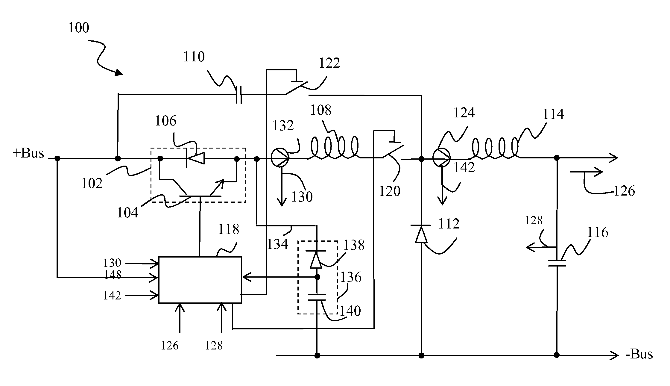
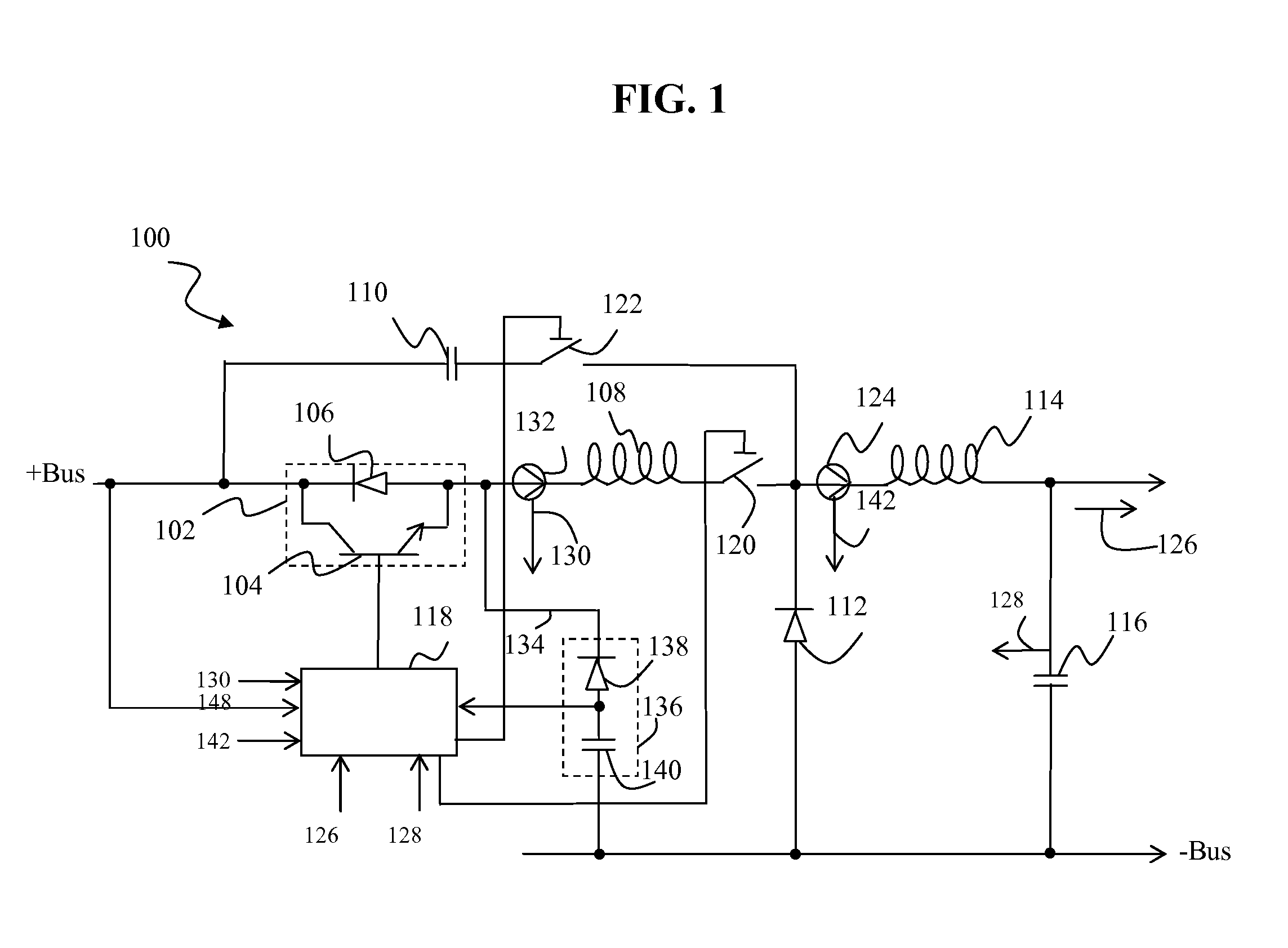
[0015]FIG. 1 illustrates a circuit diagram of an adjustable resonant buck converter circuit 100 according to some embodiments. The converter 100 includes a switching element 102 in series with a positive terminal of a DC power supply (not shown), a resonant inductor 108, an inductor switch 120, and an output inductor 114. The converter 100 also includes a branch having a capacitor 110 in series with a capacitor switch 122. The branch is parallel to the switching element 102, the resonant inductor 108, and the inductor switch 120. The switching element 102 includes a transistor 104 in parallel with a diode 106. The transistor 104 can include, for example, a bipolar junction transistor (BJT) or a field-effect transistor (FET). The diode 106 can be anti-parallel in polarity with the transistor 104. As shown in FIG. 1, the resonant inductor 108 and inductor switch 120 are positioned to the right of the switching element 102 (i.e., on the anode-side of the diode 106). However, the resona...


PUM


Abstract

A power converter includes first and second circuit modules, a first capacitor, a second diode and a control module. The first circuit module includes a switching element in parallel with a first diode. The second circuit module includes a first inductor and the first circuit module. The inductor is in series with the first circuit module. The first capacitor is in parallel with the second circuit module. The second diode includes a first terminal and a second terminal, where the first terminal is in series with the second circuit module and the first capacitor, and the second terminal is coupled to a second power terminal. The control module varies one or more of the first capacitor and the first inductor based on at least one of a current of a load circuit or an input voltage. A resonating waveform is generated by a resonant circuit of the second circuit and is used by the control module to turn off the switching element under zero-current and zero-voltage conditions.

Description

FIELD OF THE INVENTION[0001]The invention relates generally to minimizing power loss in buck converters, and to apparatuses for and methods of minimizing power loss in resonant buck converter.BACKGROUND OF THE INVENTION[0002]DC-DC converters are electronic devices used to change DC electrical power from one voltage level to another voltage level. DC-DC converters typically include thyristors, silicon-controlled full-bridge rectifiers with half and full control, and standard buck converters. However, thyristors and silicon-controlled full-bridge rectifiers suffer from high power losses and generate high current ripples. Similarly, standard buck converters are bulky and expensive, because they often include large components. For example, an output inductor of a standard buck converter typically requires high inductance to filter out the high-frequency component of an output waveform. In addition, the freewheeling diode of a standard buck converter typically is mounted on a heat sink b...

Claims


Application Information

Patent Timeline
Patent Type & Authority Applications(United States)
IPC IPC(8): G05F1/00
CPCH02M3/155H02M3/158Y02B70/1425H02M2001/0022H02M2001/0019H02M1/0019H02M1/0022Y02B70/10
Inventor TRAN, KENTIAN, FENGLEE, FRANKLINZHANG, WANGBO
Owner MKS INSTR INC
Why Eureka
Try Eureka