Multi-way sensor switch

a sensor switch and multi-way technology, applied in the field of multi-way sensor switch, can solve the problems of difficult program or commissioning of radio transmitter and receiver, difficult to adapt sensors and sensor technology to be used, and inability to work for three-way sensor applications

Inactive Publication Date: 2011-11-29
THE WATT STOPPER
View PDF66 Cites 59 Cited by
  • Summary
  • Abstract
  • Description
  • Claims
  • Application Information

AI Technical Summary

Problems solved by technology

It is difficult to adapt sensors and sensor technology to be used in three-way applications for several reasons.
Such a configuration will not work for three-way sensor applications because unlike three-way tactile switches, sensors require a continuous supervisory current to power the sensor unit such that the sensor can continuously monitor an area for motion, light level or whatever element or condition the sensor is designed to monitor.
However, radio transmitters and receivers can be difficult to program or commission in a residential setting and they tend to be expensive to manufacture.

Method used


Image

  • Multi-way sensor switch
  • Multi-way sensor switch
  • Multi-way sensor switch

Examples


Embodiment Construction

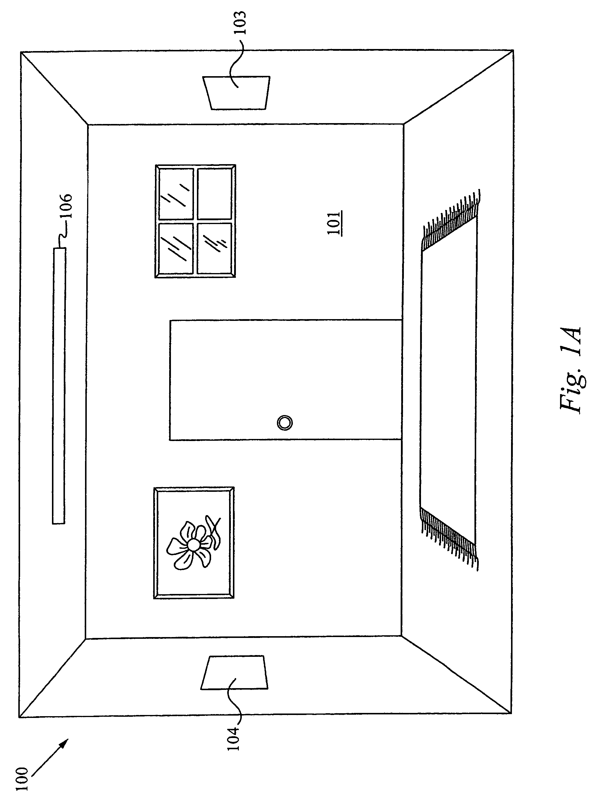
[0028]FIG. 1 shows a perspective view of a room 100 with a light management system, in accordance with the embodiments of the present invention. The light management system 100 is configured to control one or more lights 106 based on occupation of the room. The light management system includes multi-way sensor switches 103 and 104 that couple to a load circuit (not shown) that provide power for the one or more room lights 106.

[0029]Each of the multi-way sensor switches 103 and 104 include a motion sensor for sensing the presence of a person (not shown) within the room 101 and automatically controlling the one or more room lights 106 in response to a level of detected motion. Each of the multi-way sensor 10 switches also includes a manual switch for manually controlling the one or more room light 106.

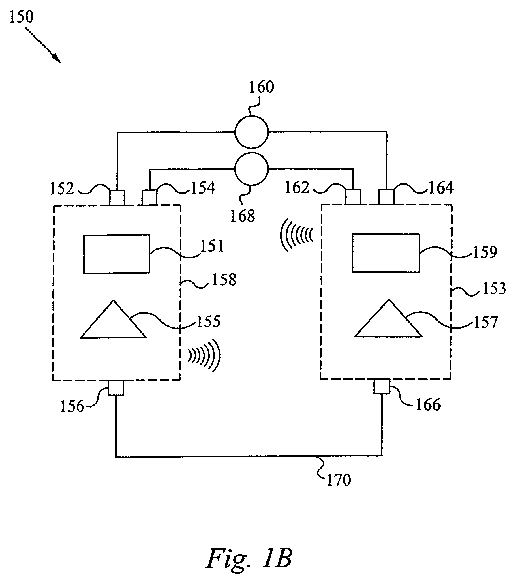
[0030]FIG. 1B shows a schematic block diagram of a light management system 150, in accordance with the embodiments of the invention. The system 150 includes a first switch unit 158 for e...


PUM


Abstract

A system for controlling a load circuit is disclosed. The system includes a plurality of multi-way sensor switches for mounting in an electrical boxes and coupling to the load circuit. Preferably, each of the multi-way sensor switches includes a tactile switch for manually opening and closing the load circuit load circuit, a built-in sensor for automatically opening and closing the load circuit in response to a level of detected motion and a micro-processor for generating status signals. The status signals are transmitted between each of the multi-way sensor switches over a traveler wire that is electrically coupled to each of the multi-way sensor switches. The micro-processor then uses the status signals to synchronize the operation of each of the multi-way sensor switches to allowing the multi-way sensor switches to operate in a true three-way fashion.

Description

RELATED APPLICATION(S)[0001]This application is a Continuation Application of the application Ser. No. 11 / 701,282, filed Jan. 31, 2007, now U.S. Pat. No. 7,436,132, which is a Continuation-in-Part application Serial No. Ser. No. 11 / 580,374, entitled “LIGHT MANAGEMENT SYSTEM DEVICE AND METHOD,” filed Oct. 12, 2006, now U.S. Pat. No. 7,405,524, which is a Continuation Application of the co-pending application Ser. No. 11 / 084,449, entitled “LIGHT MANAGEMENT SYSTEM DEVICE AND METHOD,” filed Mar. 18, 2005, now U.S. Pat. No. 7,122,976, which is a Continuation-in-Part Application of the co-pending application Ser. No. 10 / 255,659, entitled “LIGHT MANAGEMENT SYSTEM DEVICE AND METHOD,” filed Sep. 25, 2002, now U.S. Pat. No. 6,888,323. This Application also claims priority under 35 U.S.C. § 119(e) from the U.S. Provisional Patent Application Ser. No. 60 / 771,620, filed on Feb. 18, 2006, and titled “MULTI-WAY SENSOR SWITCH.” The U.S. Pat. Nos. 7,436,132, 7,405,524, 7,122,976, and 6,88,323 and th...

Claims


Application Information

Patent Timeline
Patent Type & Authority Patents(United States)
IPC IPC(8): H05B37/02
CPCH05B37/0218H05B37/0227Y02B20/44Y02B20/46H05B47/11H05B47/115Y02B20/40
Inventor NULL, JONATHAN
Owner THE WATT STOPPER
Why Eureka
Try Eureka