Drive device
a technology of a drive device and a drive shaft, which is applied in the direction of electric devices, gas pressure propulsion mountings, driver input parameters, etc., can solve the problems of relative high cranking shock, failure to quickly pass the rotational range, delay in engine speed rise, etc., to achieve fast engine speed, inexpensively realizable feedforward control, and rapid pass the resonance phenomenon rotational range
- Summary
- Abstract
- Description
- Claims
- Application Information
AI Technical Summary
Benefits of technology
Problems solved by technology
Method used
Image
Examples
first embodiment
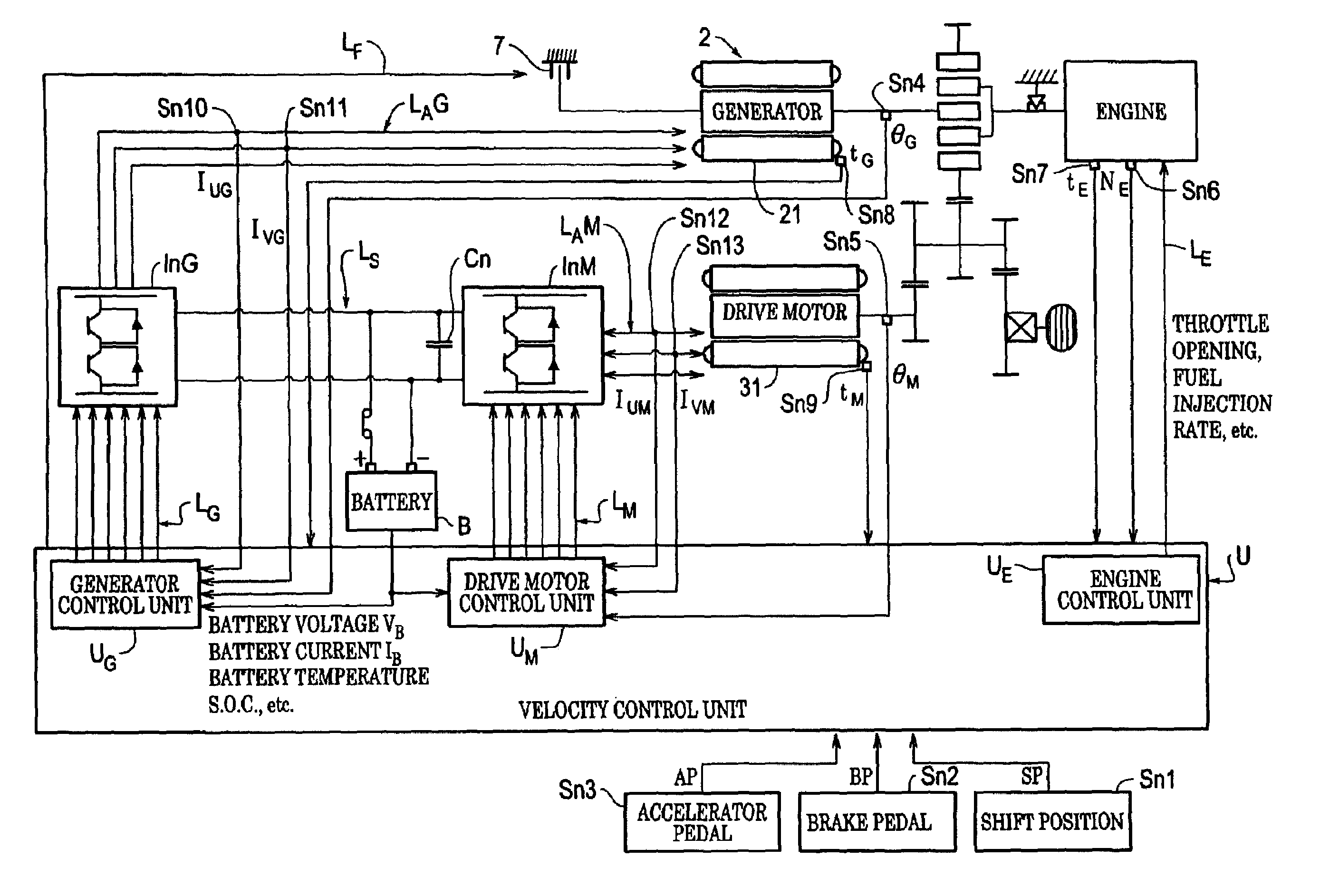
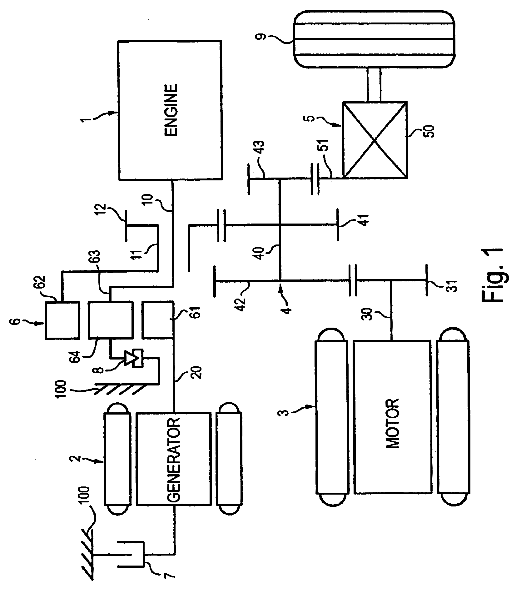
[0125]FIG. 19 shows a time chart of the control of the prepositioning control. According to this embodiment, before the cranking torque (TG c) is outputted to the generator, the crank-shaft position adjusting torque (TG p) is outputted to rotate the engine discontinuously from the A position to the B position, as specified hereinbefore, thereby to make the crank-shaft position control to the predetermined cranking starting position. This predetermined cranking starting position may be located, as will be described hereinafter, at a predetermined crank angle position by detecting it, may be warranted by a lapse of a constant time period by multiplying a predetermined torque lower than the torque necessary for starting the engine, or may combine them. Along with this, the output shaft torque fluctuation is prevented by causing the motor to output the torque which is calculated by subtracting a negating torque (TM p) for reducing the generator torque component to 0 on the output shaft ...
fifth embodiment
[0133]In a next fifth embodiment as shown in FIG. 30, therefore, a more precise torque correction is expected in a simple control by motoring in the torque control of the generator and by mapping the corresponding-negating torque. The difference between the engine start control routine shown in FIG. 30 and the engine start control routine shown in FIG. 17 resides essentially in the difference of the torque control from the aforementioned speed control of the generator. By designating the corresponding steps by similar step numbers, therefore, the description will be directed to only the differences but not to the common portions. The contents of the generator torque control of Steps S26q and S26s in this embodiment are similar to those described before with reference to FIG. 12. The fluctuating torque negating controls of Steps S26r and S26t have the following correction patterns, although the foregoing correction method shown in FIG. 21 is the first correction pattern (as will be c...
second embodiment
[0144]Although the present invention has been described in detail in connection with the various embodiments, it should not be limited to the embodiments but could be practiced in various specific manners within the scope of the claims. For example, the second embodiment, in which the prepositioning control is made at the engine stop time, could be constructed such that the prepositioning control is made at a suitable timing after the engine stop. The timing of this case is proper for the engine position control without giving any physical disorder to the driver, if it is made to the instant when the drive torque change is controlled for the accelerator manipulation or brake manipulation for the driver to change the drive demand. Moreover, the application of the invention has been described by enumerating the hybrid drive apparatus using the engine and the electric motor as its power source. However, the application of the present invention should not be limited thereto but could be...
PUM
 Abstract
Description
Claims
Application Information
 - R&D
- Intellectual Property
- Life Sciences
- Materials
- Tech Scout
- Unparalleled Data Quality
- Higher Quality Content
- 60% Fewer Hallucinations
Browse by: Latest US Patents, China's latest patents, Technical Efficacy Thesaurus, Application Domain, Technology Topic, Popular Technical Reports.
© 2025 PatSnap. All rights reserved.Legal|Privacy policy|Modern Slavery Act Transparency Statement|Sitemap|About US| Contact US: help@patsnap.com


