Origin offset calculation method of rotational position detecting device of electric motor and motor control device using the calculation method
a technology of origin offset and calculation method, which is applied in the direction of motor/generator/converter stopper, dynamo-electric gear control, motor/generator/converter stopper, etc., can solve the problem of reducing the calculation accuracy of origin offset, outputting detection errors, and not constant, so as to improve the calculation accuracy
- Summary
- Abstract
- Description
- Claims
- Application Information
AI Technical Summary
Benefits of technology
Problems solved by technology
Method used
Image
Examples
embodiment 1
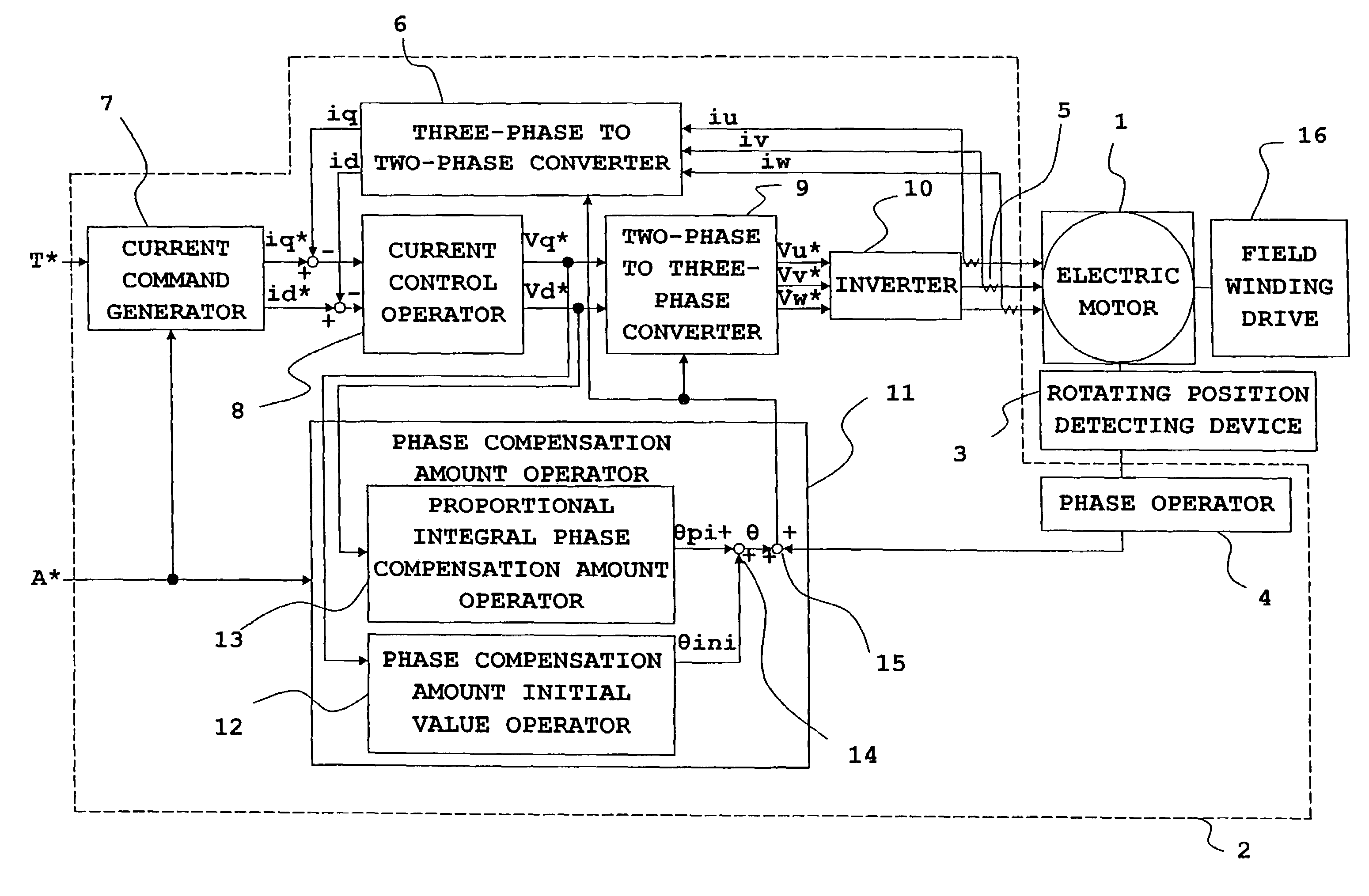
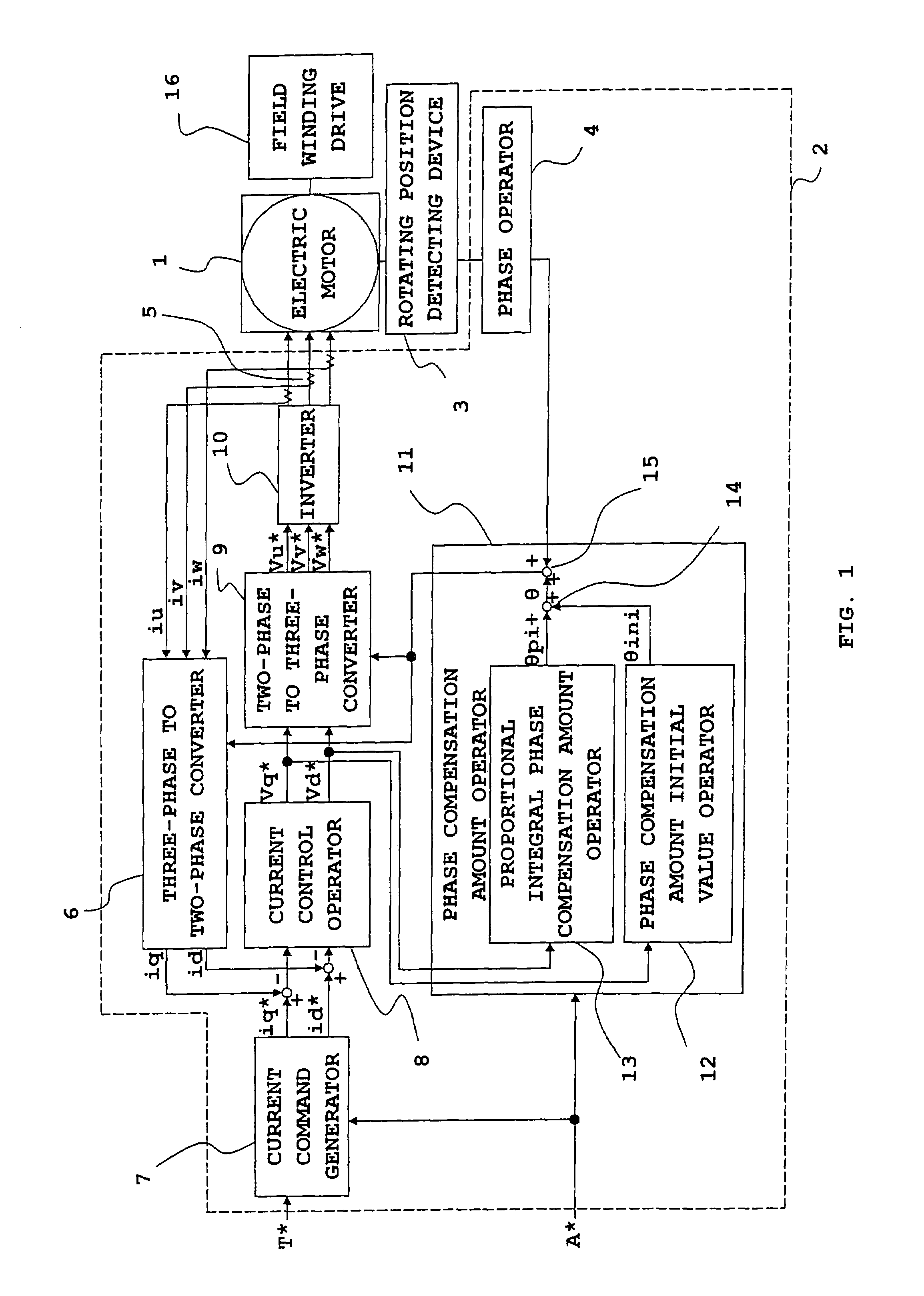
[0057]FIG. 1 is a block diagram of the entire motor control system including a motor control device for explaining an origin offset calculation method according to a first preferred embodiment of the present invention.
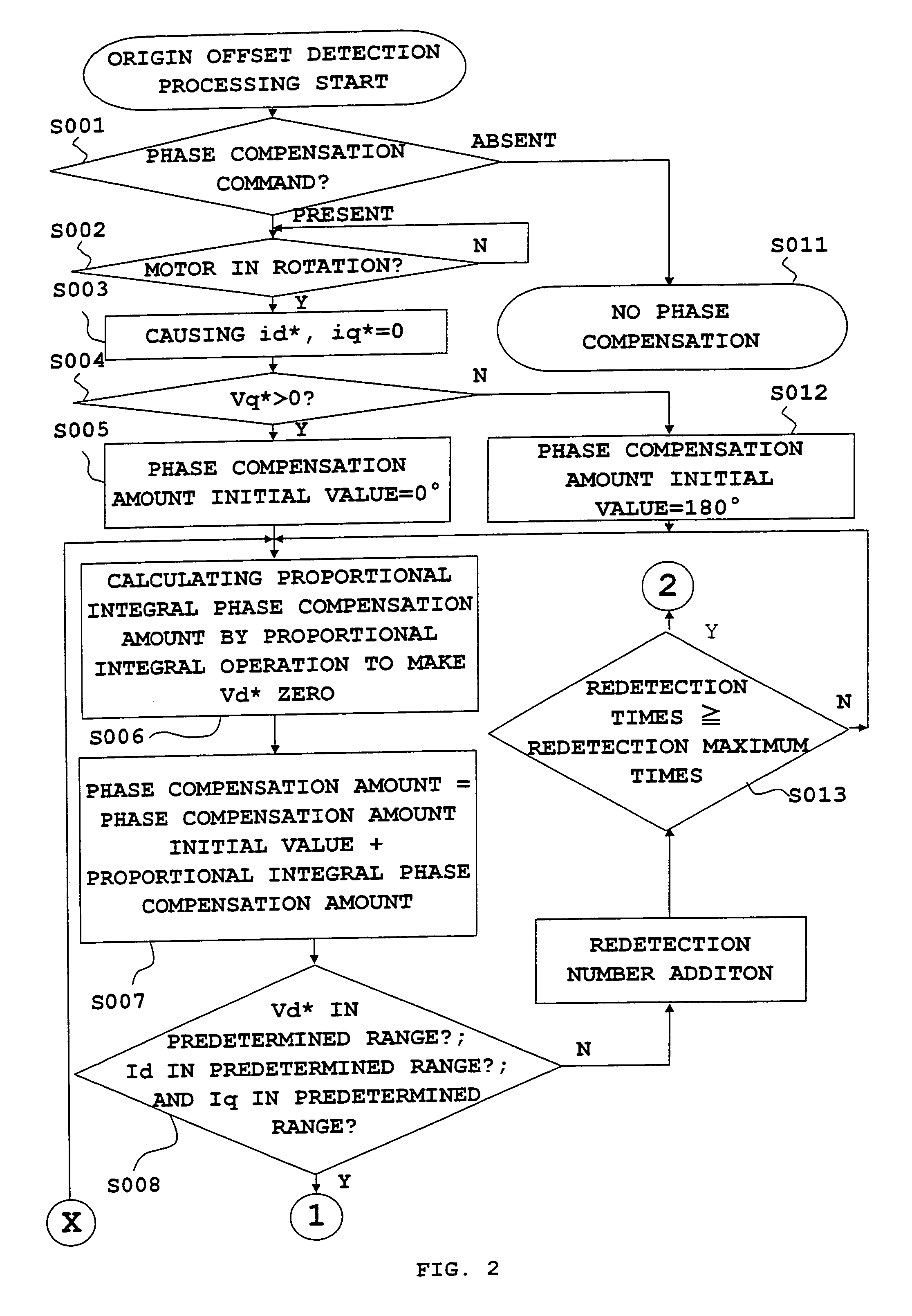
[0058]FIGS. 2 and 3 are flowcharts for explaining the origin offset calculation method of a rotational position-detecting device according to the first embodiment of this invention.
[0059]FIG. 4 is a chart showing the relation between a magnetic flux component voltage command value and a voltage command value of a component orthogonal to this component, and phases for explaining the origin offset calculation method according to the first embodiment of this invention.
[0060]With reference to FIG. 1, to a three-phase synchronous motor 1 (hereinafter referred to as electric motor) including a permanent magnet field or a winding field, a control device 2 to control the electric motor 1 is connected. A rotational position-detecting device 3 that is constructed of a resolver o...
embodiment 2
[0094]Although the calculation of an origin offset can be done as described above, it is preferable that the following processes as shown in a flowchart of FIG. 3 may be taken in order to achieve higher accuracy.
[0095]θOffset when Vd* described in the foregoing first embodiment comes to be zero is obtained, and this θoffset is integrated into a buffer, not shown (Step S009). This process is repeated n times (Step S010). Then, n times of results are added up, and a value obtained by the addition is divided by n to obtain an average value (Step S020). This average value is stored (Step S021). Thereafter, a phase compensation command A* is made OFF to return to a normal vector control of an electric motor. At this time, the average θoffset having been obtained is stored in a storage device, not shown, and an origin is compensated using this stored value at the time of normal operation.
[0096]In this case, since an average value of origin offsets θ offset with which Vd* comes to be zero ...
embodiment 3
[0097]Furthermore, higher accuracy can be achieved in the following manner. That is, in the case of presence of any detection error in the three-phase current detector, the detection error is outputted even if an actual current value is zero. Accordingly, current detected values id, iq that are obtained by the coordinate transformation with a three-phase to two-phase converter 6 will be values that periodically fluctuate.
[0098]Thus, even if the control is carried out so that the above-mentioned id, iq are compensated to be zero, voltage command values Vd*, Vq* will not be zero, but values that periodically fluctuate. However, the mentioned id, iq will be zero by the calculation of an average value as in the foregoing second embodiment. Further, an advantage is performed such that a phase difference between a rotor reference position and an origin of a rotational position-detecting device can be compensated in the state that detection error of a current detector is canceled.
[0099]Fur...
PUM
 Abstract
Description
Claims
Application Information
 - R&D
- Intellectual Property
- Life Sciences
- Materials
- Tech Scout
- Unparalleled Data Quality
- Higher Quality Content
- 60% Fewer Hallucinations
Browse by: Latest US Patents, China's latest patents, Technical Efficacy Thesaurus, Application Domain, Technology Topic, Popular Technical Reports.
© 2025 PatSnap. All rights reserved.Legal|Privacy policy|Modern Slavery Act Transparency Statement|Sitemap|About US| Contact US: help@patsnap.com


