Electro-magnetically enhanced current interrupter

a current interrupter and electromagnetic enhancement technology, applied in the direction of circuit-breaking switches for excess current, contacts, dynamo-electric relays, etc., can solve the problems of unsuitable high current use of fuse devices, low reliability, high cost, etc., and achieve the effect of reducing the number of meltable fuses, high current consumption, and high cos

Active Publication Date: 2006-04-04
PRATT & WHITNEY CANADA CORP
View PDF22 Cites 8 Cited by
  • Summary
  • Abstract
  • Description
  • Claims
  • Application Information

AI Technical Summary

Problems solved by technology

Such fuse devices, however, are unsuitable for high current use.
The devices therefore often end up being complex, expensive, heavy and of decreased reliability.
Another drawback of the meltable fuse type interrupter is that gravity is relied upon to remove the melted conductor from the circuit to thereby open the circuit.
In applications where fuse attitude or gravity may vary (e.g. airborne or space applications), these types of meltable fuses may also be unsuitable.

Method used


Image

  • Electro-magnetically enhanced current interrupter
  • Electro-magnetically enhanced current interrupter
  • Electro-magnetically enhanced current interrupter

Examples


example 1

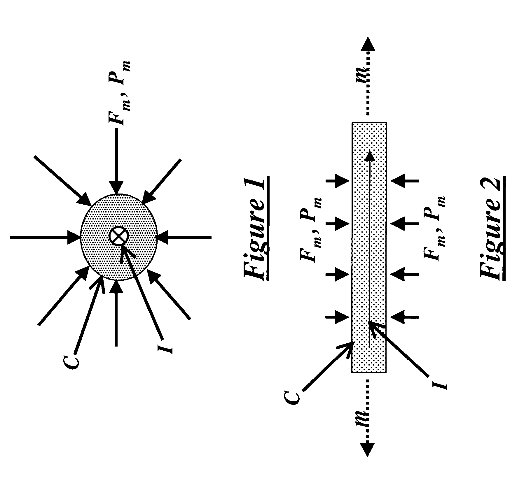
[0015]A 0.080 inch (2 mm) diameter conductor with a permeability μ=1.0 will develop a magnetic pressure of about 4 psi (27.5 kPa) at 1000 A.

example 2

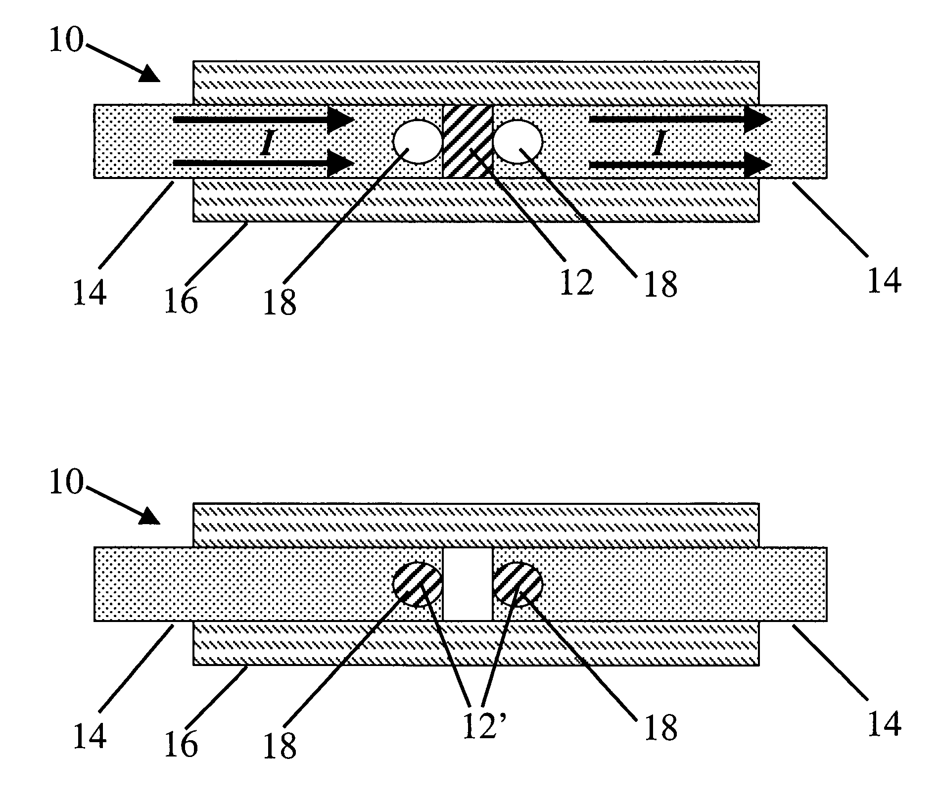
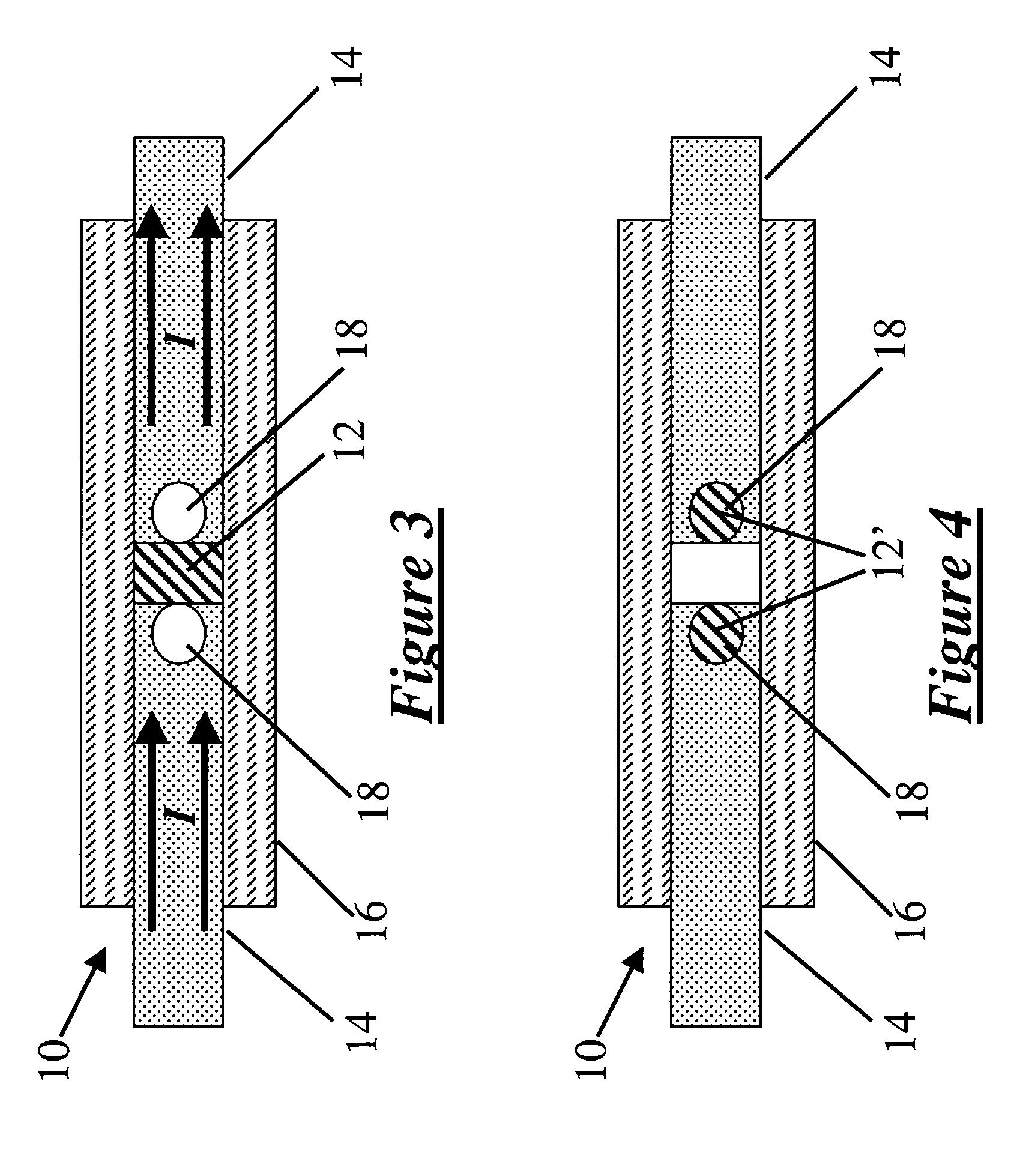
[0016]A 0.062×0.125 inch (1.5×3 mm) lead-silver solder conductor material (melting temperature 315° C.) connected to adjacent copper conductors (i.e. in a configuration like that shown in FIG. 3) can be made to rupture according to the present invention at approximately 800 A.

[0017]The force Fm and the pressure Pm is greatest at the core of the conductor, while this force and pressure at the outer periphery is zero. Thus the net effect is a axial pumping effect on a liquid conductor, which tends to squeeze the conductor in a manner roughly analogous to a tube of toothpaste being squeezed around its circumference. At normal current levels, the Fm forces are not easily measured nor are they influential on the conductor, however, when the conductor is a fluid (e.g. a melted metal) and Pm is sufficiently high, the magnetic pressure developed as a result can result in motion or flowing of the fluid which the inventor has found may be used in constructing the present interrupter.

[0018]The...


PUM


Abstract

The present invention provides an apparatus and method of interrupting the current in a circuit wherein the magnetic pressure induced by current flow through a conductor causes the conductor to flow and thereby open the associated circuit. Magnetic pressure may be derived from Lorenz equations. Gravity is not relied upon to cause the conductor material to flow. The invention may be used in circuits having high currents relative to conductor size and material selection.

Description

FIELD OF THE INVENTION[0001]The invention relates to a current interrupter for an electrical circuit, and in particular one which is well-suited for use with a high-current circuit.BACKGROUND[0002]A typical meltable fuse-type electrical interrupter includes a conductor portion which melts upon reaching a threshold current, the melting being caused by the increase in temperature associated with the current increase and the accompanying I2R effect. Once melted, the molten conductor flows, as a result of gravity and / or surface tension, away from the related conductors and the fuse thereby opens the circuit. Devices of this sort are generally described in U.S. Pat. No. 4,368,452 to Kerr Jr. and U.S. Pat. No. 4,622,534 to Bowman.[0003]Such fuse devices, however, are unsuitable for high current use. As currents increase, so too does the fusing temperature and, at very high currents, the fusing material will vapourize once the threshold current is reached, since the material cannot be remo...

Claims


Application Information

Patent Timeline
Patent Type & Authority Patents(United States)
IPC IPC(8): H01H53/00H01H85/06H01H85/38
CPCH01H85/38H01H85/06H01H2085/386
Inventor DOOLEY, KEVIN ALLAN
Owner PRATT & WHITNEY CANADA CORP
Why Eureka
Try Eureka