
Disk drive having a disk including a servo burst pattern that improves the signal to noise ratio during track following for writing

a technology of servo bursts and disk drives, applied in the field of disk drives, can solve the problem that the area of the disk recording surface occupied by servo bursts cannot be used to record user data

Inactive Publication Date: 2006-04-04
WESTERN DIGITAL TECH INC
View PDF14 Cites 116 Cited by
  • Summary
  • Abstract
  • Description
  • Claims
  • Application Information

AI Technical Summary

Benefits of technology

[0010]According to another embodiment thereof, the present invention is a method of writing to a magnetic disk drive, the magnetic disk drive including a head that includes a read transducer and a write transducer that is offset from the read transducer. The method may include the steps of providing a disk having a recording surface having embedded servo sectors that include a normal servo burst field and a circumferentially adjacent and radially offset quadrature servo burst field; positioning the read transducer over an about equal and non-zero amount of the normal burst field and the quadrature field and such that the write transducer is positioned to write over a predetermined track, maintaining the read transducer over the about equal and non-zero amount of the first normal burst field and the quadrature field while the disk rotates, and writing to the predetermined track using the write transducer.

Problems solved by technology

However, competitive pressures are such that disk drive designers continually seek to improve yield and capacity.
The area of the disk recording surface that is occupied by servo bursts cannot be used to record user data.

Method used


Image

  • Disk drive having a disk including a servo burst pattern that improves the signal to noise ratio during track following for writing
  • Disk drive having a disk including a servo burst pattern that improves the signal to noise ratio during track following for writing
  • Disk drive having a disk including a servo burst pattern that improves the signal to noise ratio during track following for writing

Examples


Embodiment Construction

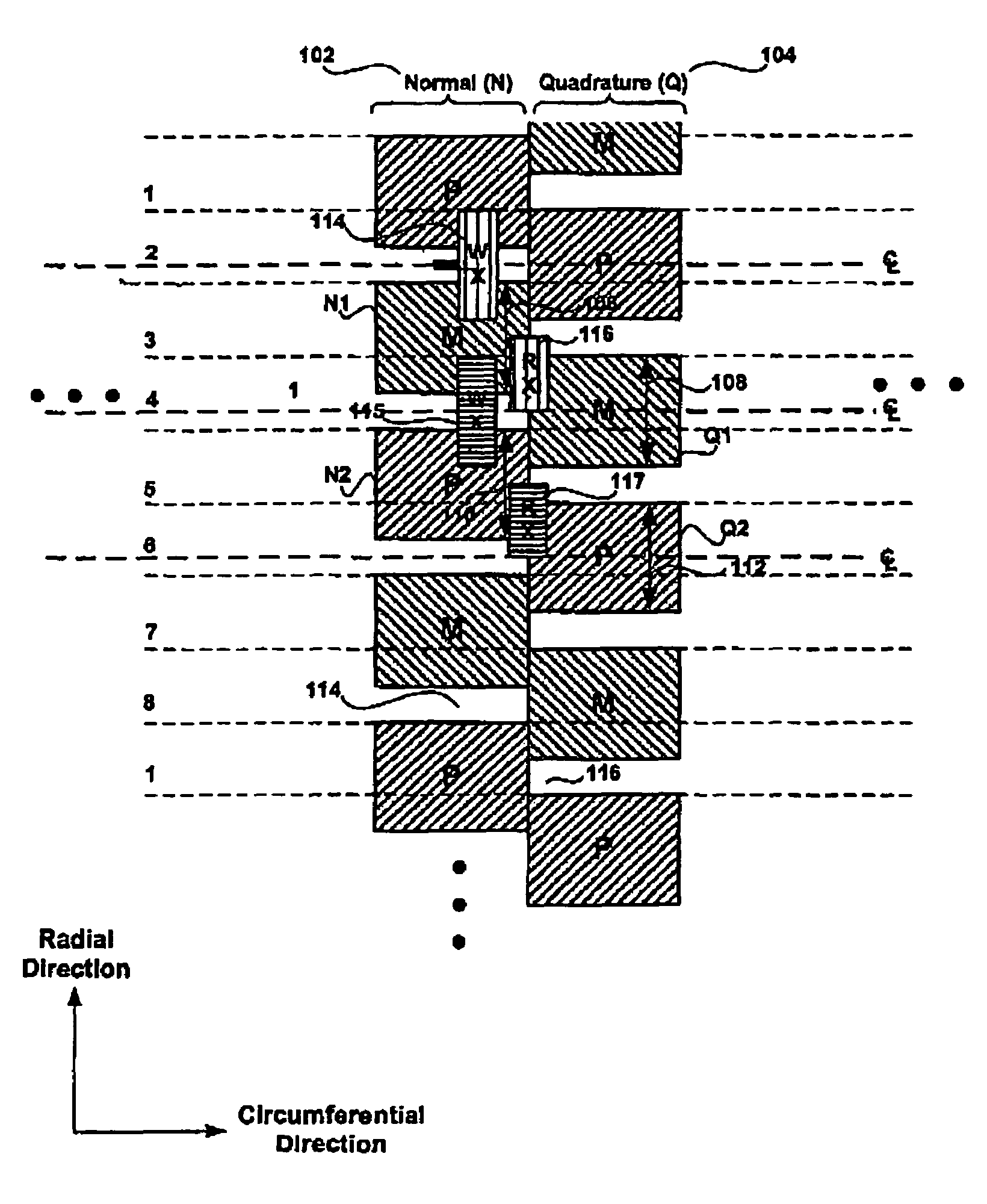
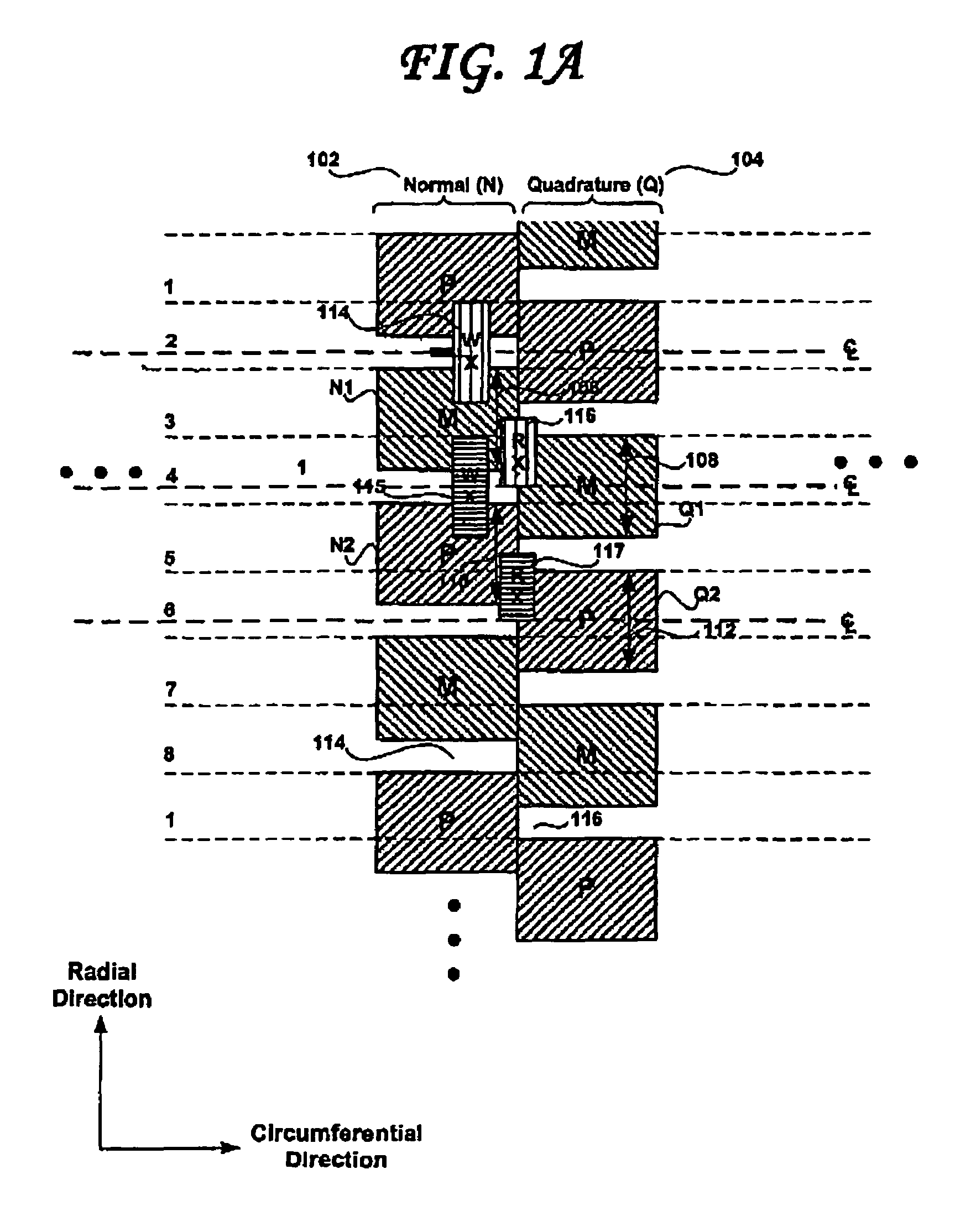
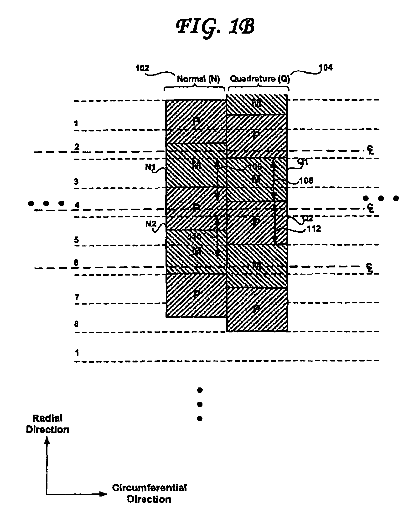
[0021]FIG. 1A shows the arrangement of normal and quadrature servo burst fields recorded on a disk of a disk drive having a sampled servo system controller, according to an embodiment of the present invention. The servo burst fields include radially aligned normal burst fields 102 and radially aligned quadrature burst fields 104. Radially adjacent normal burst fields 102 have different phases and radially adjacent quadrature burst fields 104 have different phases. According to an embodiment of the present invention, the normal and quadrature burst fields 102, 104 include servo burst fields having a first phase P and a second phase M. According to an embodiment of the present invention, the difference between the first and second phases P and M may be 180 degrees. As shown in FIG. 1A, the servo burst fields written on the disk may include a first normal burst field N1 of the first polarity M and a first quadrature burst field Q1, also of the first polarity M. A portion of the first q...


PUM

PropertyMeasurementUnit
magnetic transitionsaaaaaaaaaa
magnetic domainsaaaaaaaaaa
magnetic characteristicsaaaaaaaaaa

Abstract

A disk drive has a sampled servo system controller and a disk. The disk has a plurality a plurality servo burst fields, the plurality of servo burst field including first and second normal burst fields, and first and second quadrature burst fields. A portion of the first quadrature burst field is circumferentially contiguous with the first normal burst field and spans a portion of a radial extent of the first normal burst field. The second normal burst field is radially aligned with and away from the first normal burst field and spans a portion of a radial extent of the first quadrature burst field. The second quadrature burst field is radially aligned with and away from the first quadrature burst field and spans a portion of a radial extent of the second normal burst field. The first normal burst field and the first quadrature burst field have a same first phase and the second normal burst field and the first quadrature burst field have a same second phase. The first phase is different than the second phase.

Description

BACKGROUND OF THE INVENTION[0001]1. Field of the Invention[0002]The present invention relates to disk drives and to the pattern of the servo burst fields written to disks used in such disk drives.[0003]2. Description of the Prior Art and Related Information[0004]In a conventional disk drive, each recording surface of each magnetic disk contains a plurality of concentric data tracks angularly divided into a plurality of data sectors. In addition, special servo information is provided on this disk or another disk to determine the position of the head. The most popular form of servo is called “embedded servo” wherein the servo information is written on this disk in a plurality of servo sectors that are angularly spaced from one another and interspersed between data sectors around the track. Each servo sector generally comprises a track identification (ID) field and a group of servo bursts that the servo control system samples to align the transducer head with or relative to a particula...

Claims


Application Information

Patent Timeline
Patent Type & Authority Patents(United States)
IPC IPC(8): G11B5/09
CPCG11B5/59688
Inventor KUPFERMAN, HANAN
Owner WESTERN DIGITAL TECH INC
Learn More