Apparatus for attaching electrical components to a vehicle

a technology for electrical components and vehicles, applied in the direction of cell components, electric devices, cell component details, etc., can solve the problems of difficult to obtain sufficient rigid mounting structures for electrical power train components, and achieve the effect of increasing the rigidity of the rear floor pan

Active Publication Date: 2006-04-11
SUZUKI MOTOR CORP
View PDF16 Cites 50 Cited by
  • Summary
  • Abstract
  • Description
  • Claims
  • Application Information

AI Technical Summary

Benefits of technology

[0012]Therefore, the first and second frames function as reinforcing members that increase the rigidity of the rear floor pan to provide an adequate foundation for the installation of heavy electrical drive train components.

Problems solved by technology

As the floor pan is often incapable of rigidly supporting the weight of these components, a sufficiently rigid mounting structure for electrical power train components has been difficult to obtain.

Method used


Image

  • Apparatus for attaching electrical components to a vehicle
  • Apparatus for attaching electrical components to a vehicle
  • Apparatus for attaching electrical components to a vehicle

Examples


Embodiment Construction

[0020]The particulars shown herein are by way of example and for purposes of illustrative discussion of the embodiments of the present invention only and are presented in the cause of providing what is believed to be the most useful and readily understood description of the principles and conceptual aspects of the present invention. In this regard, no attempt is made to show structural details of the present invention in more detail than is necessary for the fundamental understanding of the present invention, and the description is taken from the drawings making apparent to those skilled in the art how the forms of the present invention may be embodied in practice.

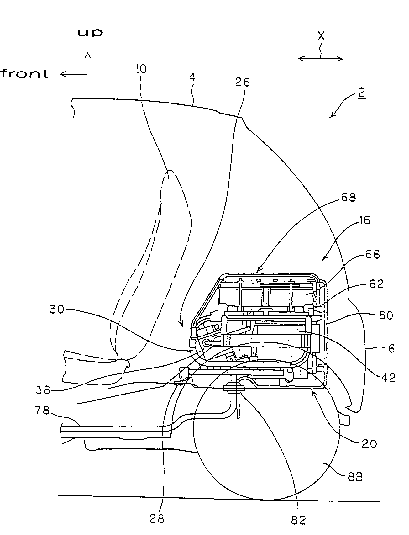
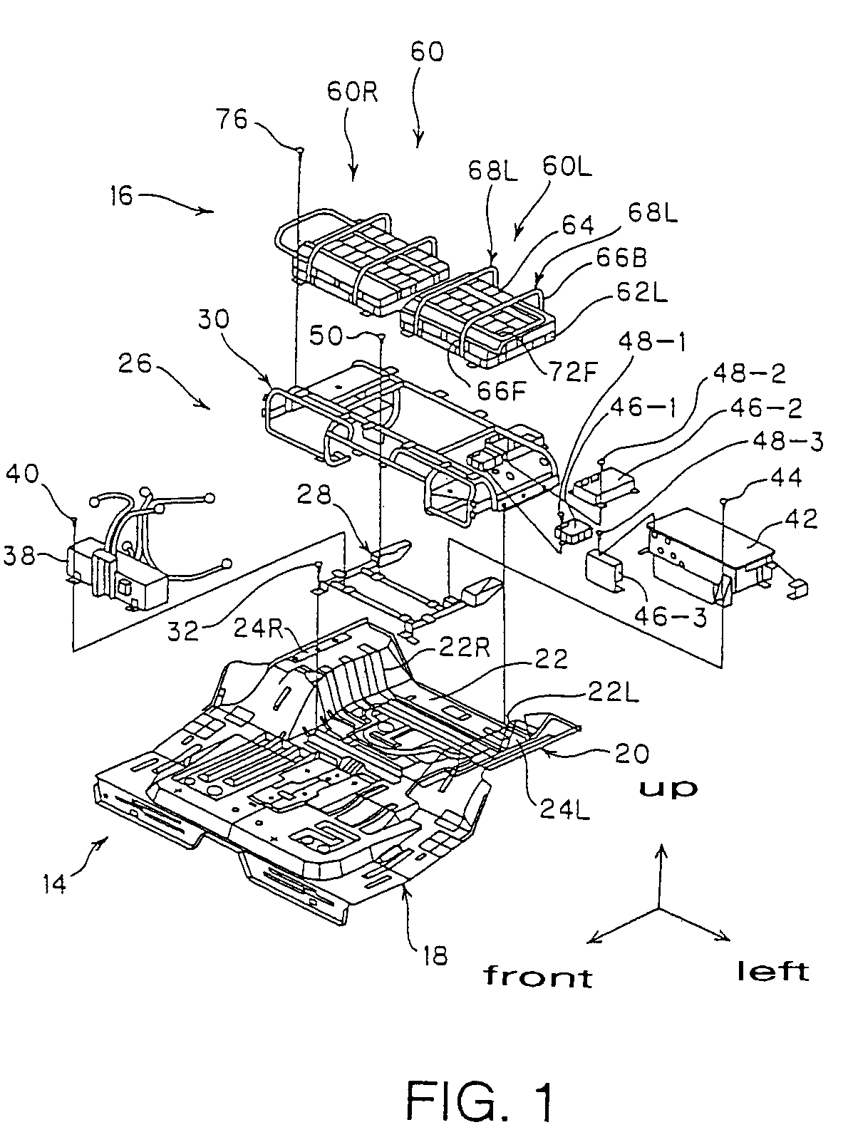
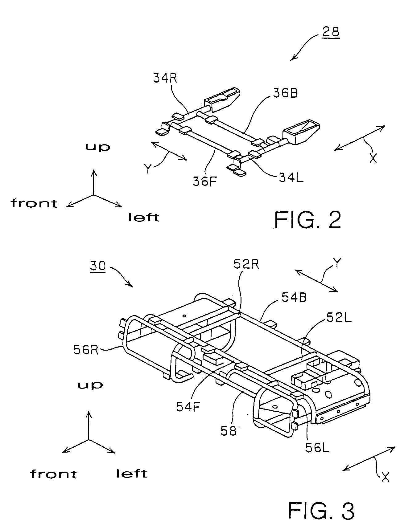
[0021]The invention provides for a structure in which first and second frames, to which heavy electrical drive train components are mounted, function as reinforcing members that increase the rigidity of the rear floor pan in order to provide adequate support for the aforesaid components.

[0022]FIGS. 1 through 6 illustrate a...


PUM

PropertyMeasurementUnit
rigidityaaaaaaaaaa
weightaaaaaaaaaa
stressaaaaaaaaaa

Abstract

A structure for mounting electrical components to a vehicle. The structure includes a rear floor pan incorporating a U-shaped part transversely centered in the vehicle. Floor pan wing panels extend from each end of the U-shaped part and connect to vehicle side panels. An electrical component mounting rack includes a first frame attached to the U-shaped floor panel part, and a second frame attached to the top of the first frame and also to the floor pan wing panels. An electrical inverter device is mounted to the first frame and batteries are mounted to the second frame. The first and second frames form a structure that reinforces the rear floor pan in a manner capable of adequately supporting heavy electrical drive train components.

Description

BACKGROUND OF THE INVENTION[0001]1. Field of the Invention[0002]The present invention relates to an apparatus for attaching electrical components to a vehicle. More specifically, the present invention relates to an apparatus for attaching electrical components to a vehicle in which the apparatus increases the rigidity of the rear floor pan of the vehicle.[0003]2. Description of Background Information[0004]Electrical power train components have been conventionally mounted to a vehicle by attaching batteries and other heavy electrical components directly to the rear floor pan of the vehicle. As the floor pan is often incapable of rigidly supporting the weight of these components, a sufficiently rigid mounting structure for electrical power train components has been difficult to obtain.[0005]The prior art includes structures that mount electrical drive train components to a rear floor pan behind a vehicle seat. For instance, Japanese Unexamined Patent No. 2002-205556 (see pages 4 and 5...

Claims


Application Information

Patent Timeline
Patent Type & Authority Patents(United States)
IPC IPC(8): B60R16/04B62D25/20B60K1/04B60R11/00B60R11/02B60R16/02H01M50/204H01M50/244H01M50/249
CPCB60K1/04B60L3/0007B60L15/007B60R11/00B60R11/02B60L11/1877B60R16/0215B60K2001/0416Y02T10/705B60R2011/0012Y10S903/907Y10S903/952Y02T10/7005B60L50/66Y02T10/64Y02T10/70Y02E60/10H01M50/204H01M50/249H01M50/244
Inventor AWAKAWA, HIROBUMI
Owner SUZUKI MOTOR CORP
Why Eureka
Try Eureka