Apparatus for removing particulates from a gas stream

a technology of particulates and apparatus, applied in the field of environmental control, to achieve the effect of reducing nois

Inactive Publication Date: 2006-04-11
WYNN II RICHARD
View PDF20 Cites 4 Cited by
  • Summary
  • Abstract
  • Description
  • Claims
  • Application Information

AI Technical Summary

Benefits of technology

[0010]The inlet channel may include an inlet ramp that constricts the effective size of the inlet channel, and assists in initially removing large pieces of debris. The perforated sheet may extend underneath the inlet ramp, so as to maximize the available area of the sheet.
[0011]The device may also include wave breaks, above and / or below the perforated sheet, which minimize the effect of liquid waves formed in the reservoir and in the liquid located immediately above the perforated sheet.
[0015]The invention has the further object of providing an economical apparatus and method for removing particulates from a gas stream.
[0016]The invention has the further object of providing a wet dust collector that reduces waves that may form in the liquid scrubbing medium.
[0017]The invention has the further object of reducing noise associated with a wet dust collector.

Problems solved by technology

A major disadvantage of wet gas scrubbers is that they generally require a pump to circulate water through the system.

Method used


Image

  • Apparatus for removing particulates from a gas stream
  • Apparatus for removing particulates from a gas stream
  • Apparatus for removing particulates from a gas stream

Examples


Embodiment Construction

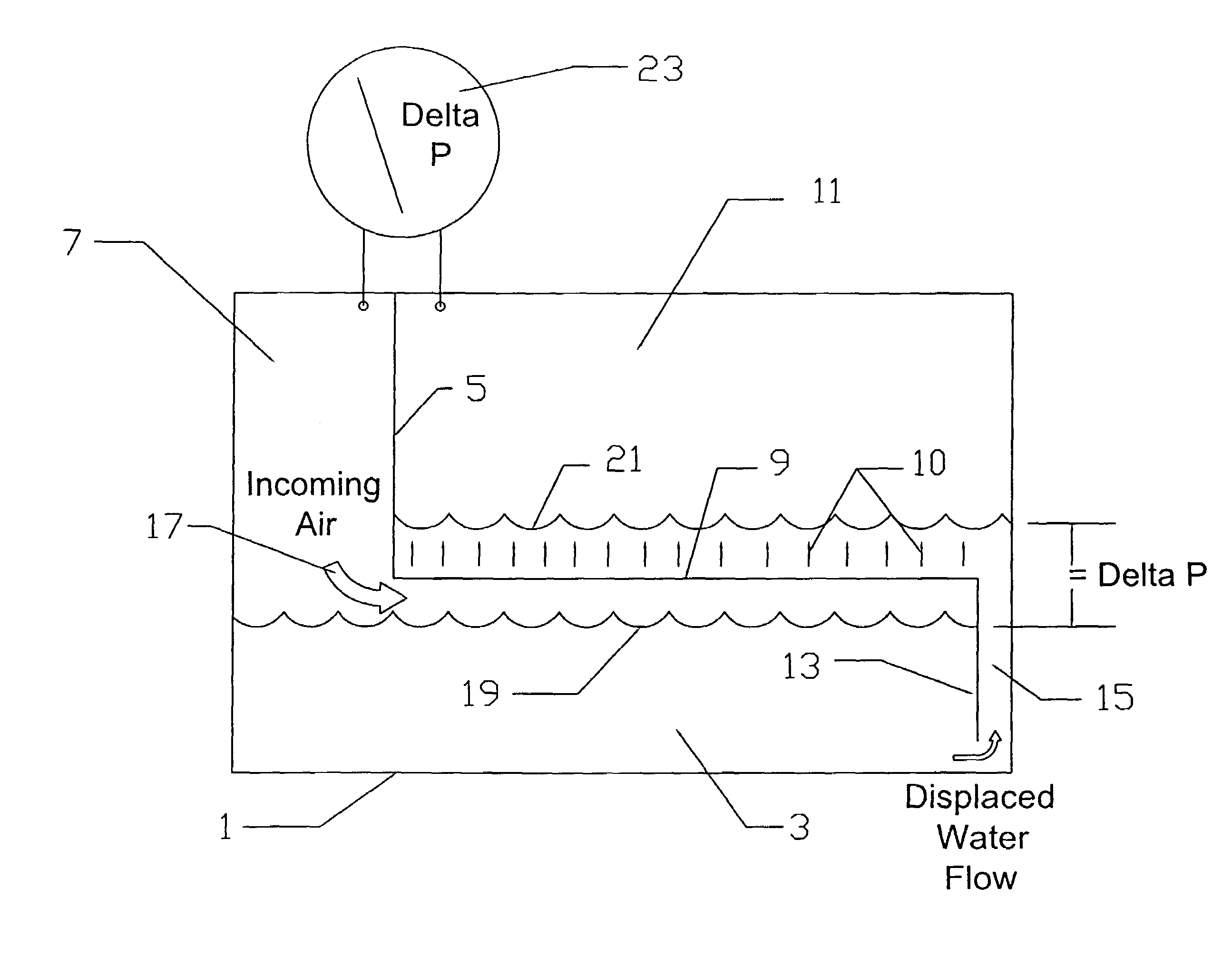
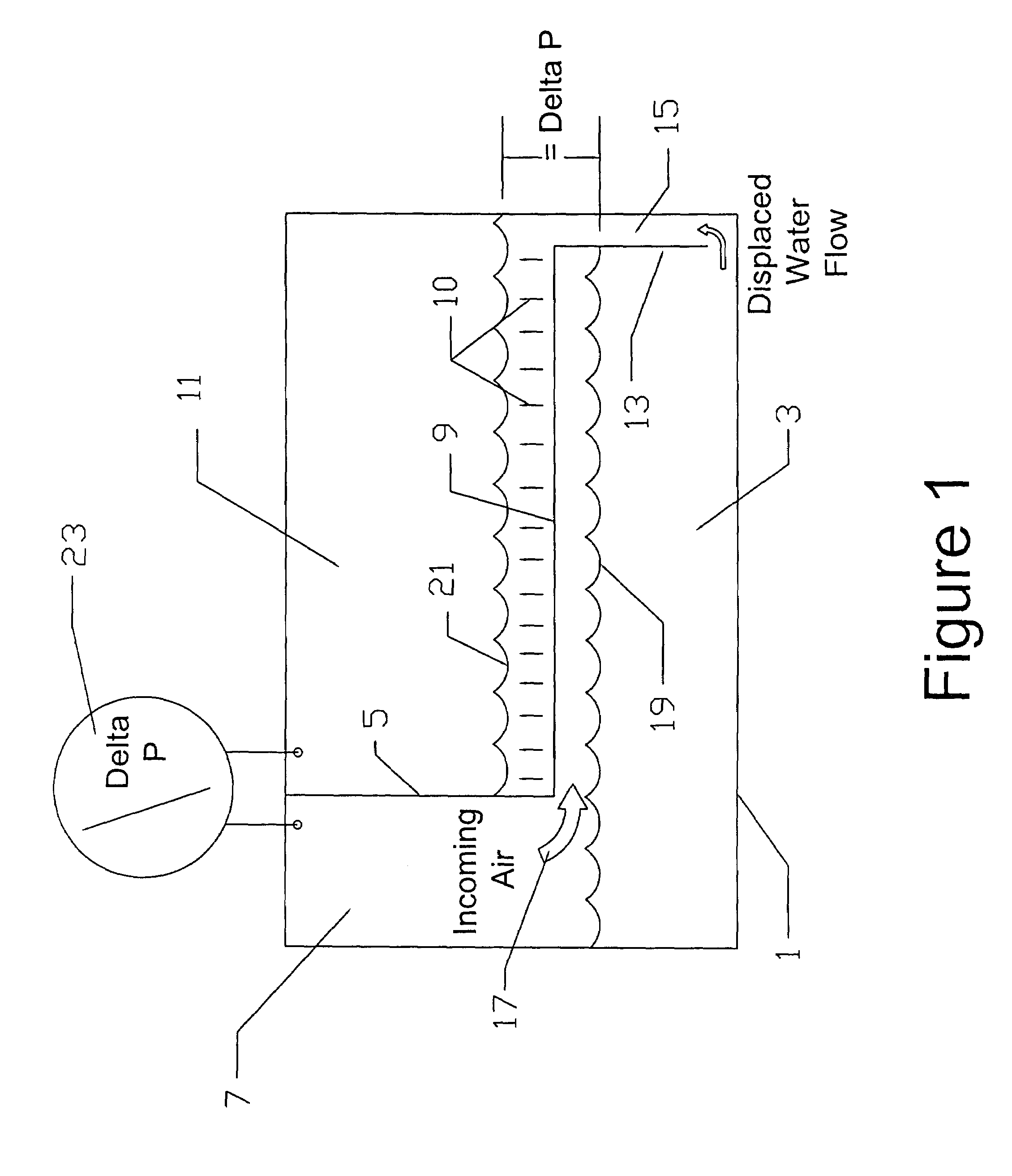
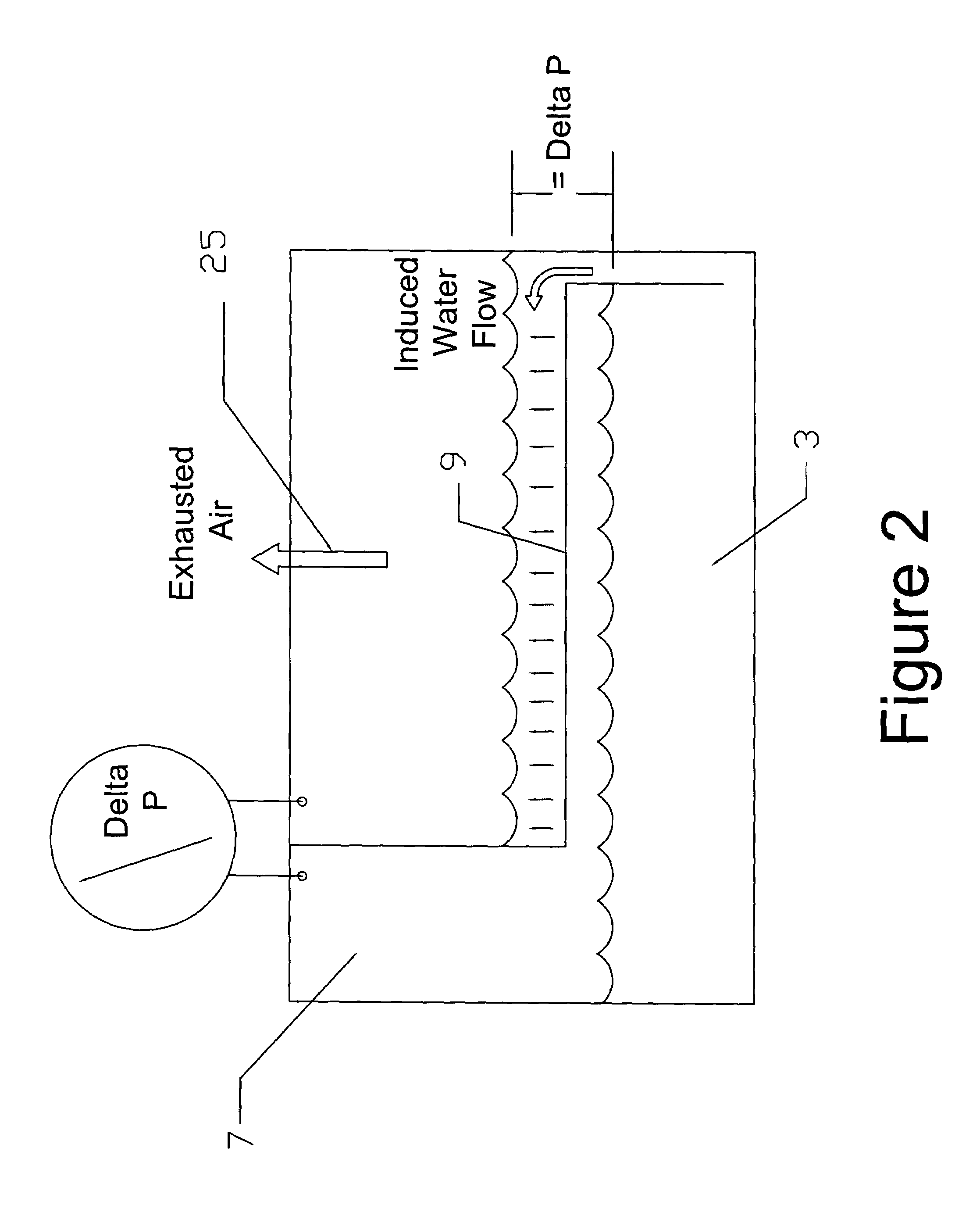
[0031]The schematic diagrams of FIGS. 1 and 2 show the present invention in its simplest form. A container or vessel 1 defines a sump or reservoir which holds liquid 3, which is normally water. A perforated sheet 9 lies above the reservoir. The short vertical lines 10 symbolize the air jets and bubbles, as they pass through the perforations. A baffle 5 separates inlet channel 7 from outlet area 11 above the perforated sheet. A baffle 13 defines liquid transfer channel 15. The baffle 13 does not extend to the bottom of the reservoir, thereby providing fluid communication between the reservoir and the liquid transfer channel.

[0032]As shown in the figure, the liquid transfer channel is narrow relative to the width of the reservoir. The width of the reservoir is, in general, many times the width of the liquid transfer channel.

[0033]The liquid transfer channel may take other forms. Instead of having a channel of the type shown in the drawings, one could instead use a slot, a tube, or oth...


PUM

PropertyMeasurementUnit
velocityaaaaaaaaaa
velocitiesaaaaaaaaaa
diameteraaaaaaaaaa

Abstract

Particulates are removed from a gas stream by contact with a liquid. The gas stream is conveyed through an inlet channel, towards a liquid reservoir which is located below a perforated sheet. Gas flowing through holes in the sheet creates a pressure drop between the inlet channel and an outlet area above the sheet. This pressure drop draws liquid up from the reservoir, through a relatively narrow liquid transfer channel, so that the liquid covers the sheet. Gas flowing through holes in the sheet therefore encounters a layer of liquid located immediately above the sheet. Particulates in the gas are captured by the liquid in this layer. The device requires no pump for moving the liquid through the system, the liquid being transferred solely as a result of the pressure drop induced by the flow of gas.

Description

BACKGROUND OF THE INVENTION[0001]This invention relates to the field of environmental control, and provides a device which removes particulates or other materials from a gas stream. In particular, the present invention comprises a wet gas scrubber in which water is the preferred medium for removing contaminants from air.[0002]Environmental concerns have prompted the development of many devices for removing contaminants from the air. Such devices are used in industry, such as in cleaning air streams before they are released to the outside through a smoke stack. They are used in commercial settings, such as in cleaning air that is exhausted from apartment buildings or office buildings. And they are also found in smaller scale applications, such as in cleaning the air in small businesses or homes.[0003]It has long been known to remove particulates from air by contacting the air with water, and allowing the water to capture and retain the particulates. In effect, water acts as a filtrat...

Claims


Application Information

Patent Timeline
Patent Type & Authority Patents(United States)
IPC IPC(8): B01F3/04B01D47/02
CPCB01D47/024B01D47/021
Inventor WYNN, II, RICHARD
Owner WYNN II RICHARD
Why Eureka
Try Eureka