Structured packing with increased capacity

a structured packing and capacity technology, applied in the direction of spades, lighting and heating apparatus, separation processes, etc., can solve the problems of premature degradation of mass transfer performance, limited capacity of structured packing, and high cost of mesh type packing over most foil type packing, etc., to achieve the effect of increasing the capacity of the exchange column

Inactive Publication Date: 2006-04-11
AIR PROD & CHEM INC
View PDF30 Cites 13 Cited by
  • Summary
  • Abstract
  • Description
  • Claims
  • Application Information

AI Technical Summary

Problems solved by technology

It also is well-known in the prior art that mesh type packing helps spread liquid efficiently and gives good mass transfer performance, but mesh type packing is much more expensive than most foil type packing.
Usually the capacity of structured packing is limited by flooding.
Mass transfer flooding, which is the premature degradation in mass transfer performance prior to the onset of hydraulic flooding, occurs when the mass transfer efficiency of the column starts deteriorating rapidly with the increase of vapor and / or liquid flow in the column.
Although these prior art modifications may improve the capacity of structured packing, those designs still suffer from a problem of uncontrolled and random gaps between adjacent layers of structured packing, which gaps are a result of the manufacturing methods used for conventional structured packing sheets.
The uncontrolled gaps between adjacent layers are due to a less than perfect alignment of the individual structured packing elements or sheets within the layers.
This can lead to performance degradation in terms of both mass transfer and pressure drop, especially at high flow rates.

Method used


Image

  • Structured packing with increased capacity
  • Structured packing with increased capacity
  • Structured packing with increased capacity

Examples


Embodiment Construction

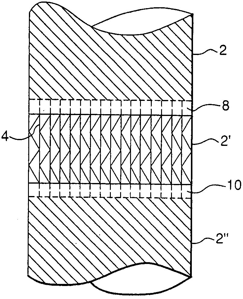
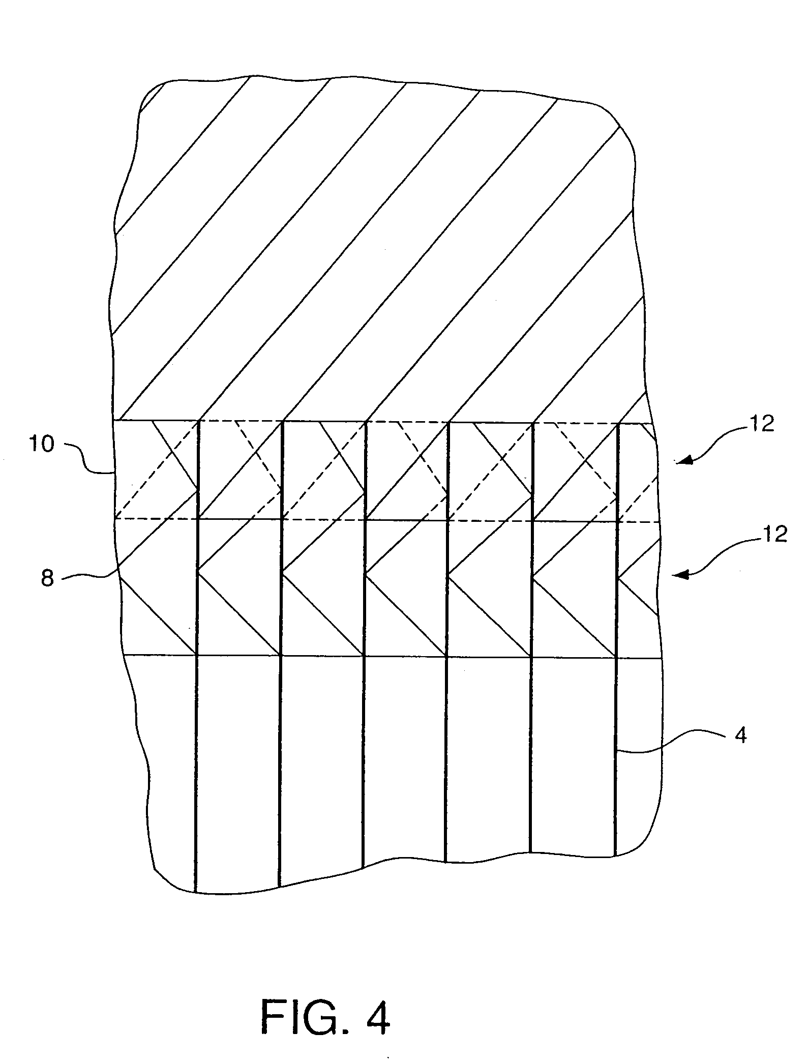
[0047]Applicants have discovered that by making adjacent layers of structured packing to intermesh, they can delay the onset of mass transfer flooding as well as reduce the pressure drop of the structured packing, thereby increasing the capacity of the structured packing. This occurs because of an improvement in the drainage of liquid between the layers and a decrease in the entrainment of liquid droplets into the packing channels.

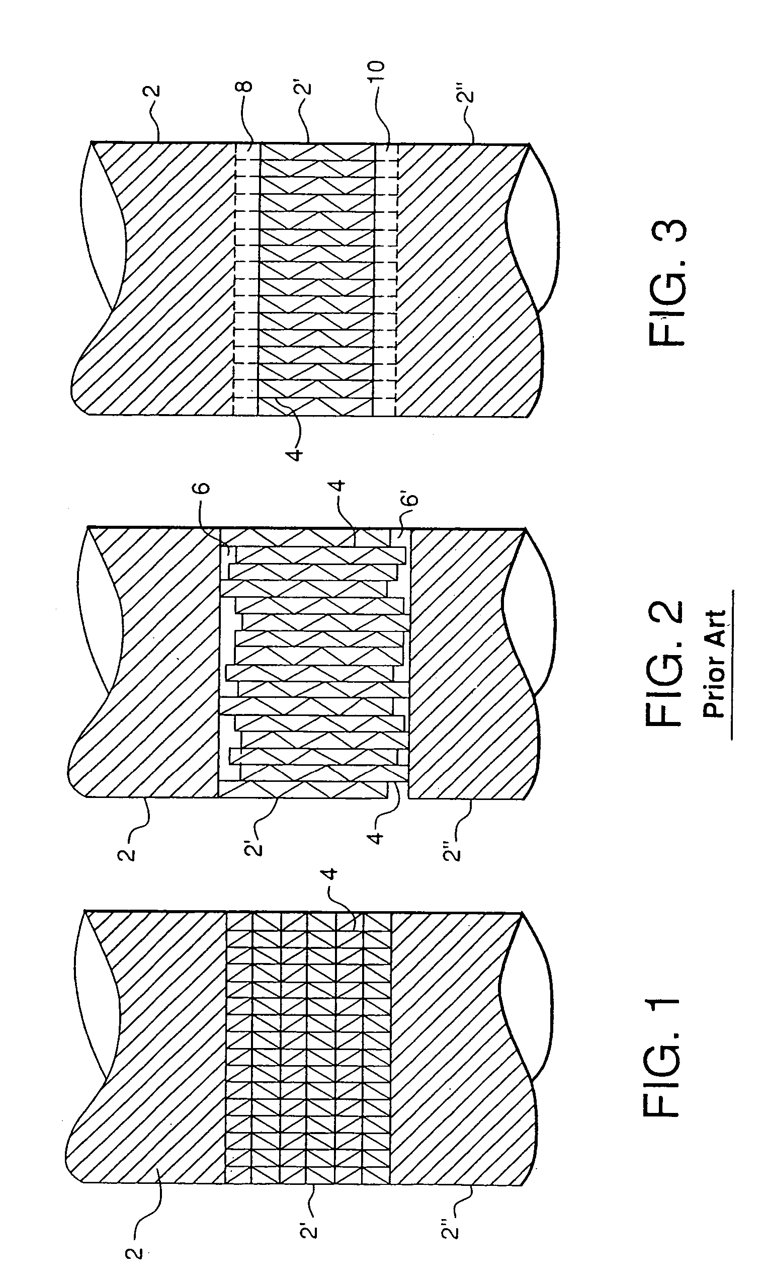
[0048]FIGS. 1 and 2 illustrate multiple layers (2, 2′, 2″) of structured packing arranged as the layers might be in an exchange column (not shown). When individual sheets 4 of structured packing are assembled into layers of packing, the sheets usually are slightly misaligned in the vertical direction due to imperfections in the manufacturing process. This is shown in the schematic diagram of FIG. 2 in which the misalignments are exaggerated for the purpose of illustration. Such misalignment causes gaps (6, 6′) to appear between adjacent layers of packing i...


PUM

PropertyMeasurementUnit
massaaaaaaaaaa
mass transferaaaaaaaaaa
sizeaaaaaaaaaa

Abstract

A structured packing element has at least one edge adapted to intermesh with an edge of at least one other structured packing element. The structured packing elements may be used in a packed section in an exchange column which includes: a first layer of structured packing including a first structured packing element having an upper edge adapted to intermesh with a generally vertically adjacent lower edge of a second structured packing element; and a second layer of structured packing located above the first layer of structured packing, the second layer including the second structured packing element having the lower edge adapted to intermesh with the generally vertically adjacent upper edge of the first structured packing element. The upper edge of the first structured packing element intermeshes with the lower edge of the second structured packing element.

Description

CROSS REFERENCE TO RELATED APPLICATIONS[0001]This is a divisional of application Ser. No. 10 / 404,803, filed on Mar. 31, 2003.BACKGROUND OF THE INVENTION[0002]The present invention relates to structured packing and to methods for installing such packing in an exchange column to provide increased capacity. The structured packing has particular application in cryogenic air separation processes, although it also may be used in other heat and / or mass transfer processes that can utilize structured packing.[0003]The term, “column” (or “exchange column”) as used herein, means a distillation or fractionation column or zone, i.e., a column or zone wherein liquid and vapor phases are counter currently contacted to effect separation of a fluid mixture, such as by contacting of the vapor and liquid phases on packing elements or on a series of vertically-spaced trays or plates mounted within the column.[0004]The term “column section” (or “section”) means a zone in a column filling the column diam...

Claims


Application Information

Patent Timeline
Patent Type & Authority Patents(United States)
IPC IPC(8): B01F3/04B01J19/32F25J3/04
CPCB01J19/32F25J3/04909B01J2219/3221B01J2219/32217B01J2219/32227B01J2219/32244Y10S261/72B01J2219/32272B01J2219/326B01J2219/3325B01J2219/32258A01B25/00A01B49/06A01C7/123
Inventor MESKI, GEORGE AMIRSUNDER, SWAMINATHAN
Owner AIR PROD & CHEM INC
Why Eureka
Try Eureka