Cable sleeve and method of installation

a technology of cable sleeve and cable, which is applied in the direction of insulated conductors, cables, instruments, etc., can solve the problems of cables, much like all optical cables, are sensitive to sharp bends, etc., and achieve the effect of preventing snagging with outside obstructions

Inactive Publication Date: 2006-04-11
DAFOCOM SOLUTIONS
View PDF8 Cites 51 Cited by
  • Summary
  • Abstract
  • Description
  • Claims
  • Application Information

AI Technical Summary

Benefits of technology

[0008]According to the present invention there is provided a bend / stress relief sleeve kit for installation over an existing fibre optic cable / fibre optic cable connector assembly without disassembly or modification of the existing fibre optic cable / fibre optic cable connector assembly, the kit comprising: an inner spiral wrap for wrapping the existing fibre optic cable / fibre optic cable connector assembly, overlapping at least part of the fibre optic cable connector and extending over the fibre optic cable, the spiral wrap providing bend relief; an outer mesh having a tubular passageway, for overlapping at least part of the fibre optic cable connector and extending over the fibre optic cable, the outer mesh covering at least a substantial portion of the inner spiral wrap; first fastening means for fastening the outer mesh to the fibre optic cable connector; and second fastening means for fastening the outer mesh to the fibre optic cable; whereby the combination of the outer mesh, the first fastening means and the second fastening means provides tensile strength to the existing fibre optic cable / fibre optic cable connector assembly; and whereby the outer mesh provides a smooth exterior surface to prevent snagging with outside obstructions.
[0009]In another embodiment of the invention there is provided a method of installing a bend / stress relief sleeve over an existing fibre optic cable / fibre optic cable connector assembly, without modifying or disassembling the existing fibre optic cable / fibre optic cable connector assembly, comprising the steps of: wrapping a length of an inner spiral wrap around the existing fibre optic cable / fibre optic cable connector assembly, overlapping at least part of the fibre optic cable connector and extending over the fibre optic cable, the spiral wrap providing bend relief; inserting the wrapped existing fibre optic cable / fibre optic cable connector assembly into an outer mesh having a tubular passageway, overlapping at least part of the fibre optic cable connector and extending over the fibre optic cable, the outer mesh covering at least a substantial portion of the inner spiral wrap; fastening the outer mesh to the fibre optic cable connector using a first fastening means; and fastening the outer mesh to the fibre optic cable using a second fastening means; whereby the combination of the outer mesh, the first fastening means and the second fastening means provides tensile strength to the existing fibre optic cable / fibre optic cable connector assembly; and whereby the outer mesh provides a smooth exterior surface to prevent snagging with outside obstructions.

Problems solved by technology

Military grade fibre cables are quite rugged in construction.
However, these cables, much like all optical cables, are sensitive to sharp bends, many breakages occurring at the connector-to-cable junction.
These breakages occur because the weight to cable diameter ratio of the connector is quite large.
A second problem occurs upon the retrieval of the cables.
Connectors, due to their large size and heavy weight, often become entangled or snagged on and around ground obstructions resulting in the breakage of the fibre at the connector-to-cable junction.

Method used


Image

  • Cable sleeve and method of installation
  • Cable sleeve and method of installation
  • Cable sleeve and method of installation

Examples


Embodiment Construction

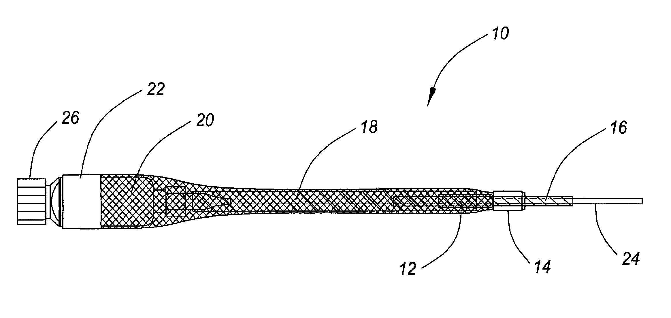
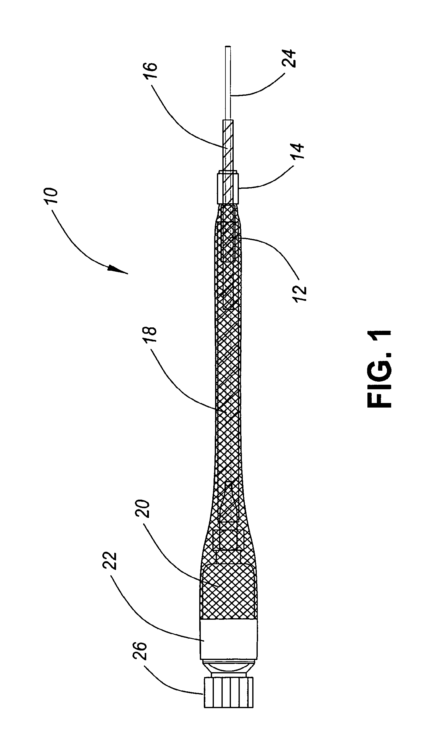
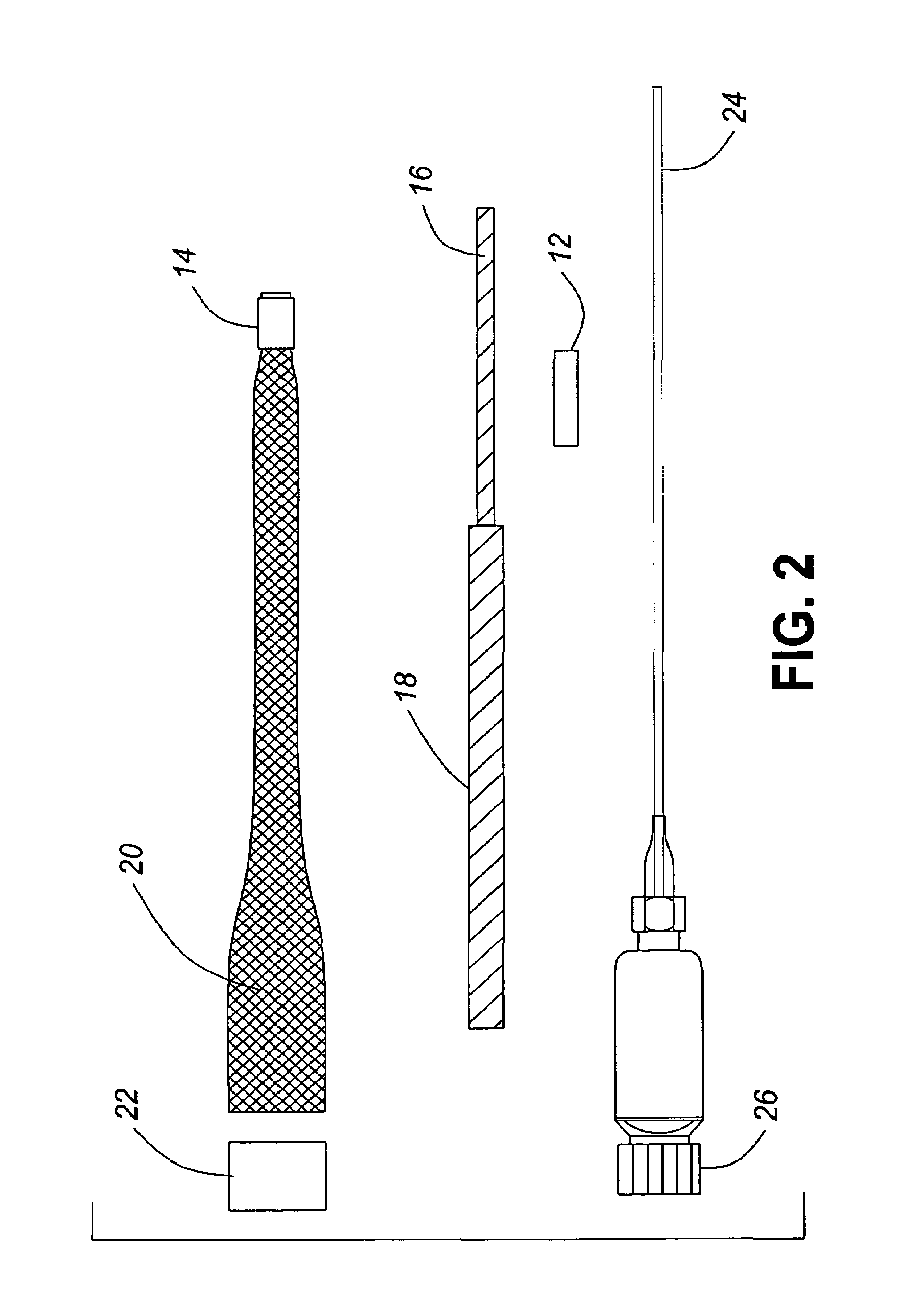
[0025]The bend / stress relief sleeve of the invention addresses the problems in the art. FIGS. 1, 2 and 3 present various side-elevation views and cross-sections of the invention. FIG. 4 presents a flow chart of a method of installation, while FIGS. 5 through 13 present perspective and detailed views of the bend / stress relief sleeve as it is being installed on an existing fibre optic cable / fibre optic cable connector assembly. The bend / stress relief of the invention can be installed on an existing cable / connector assembly without having to disassemble the cable / connector assembly. In addition to providing bend relief, the invention mechanically joins the fibre optic connector or Electro-Optical (E / O) module to the cable, thereby providing stress relief.

[0026]The bend / stress relief sleeve 10 of FIGS. 1, 2 and 3 uses a combination of:[0027]two soft non-sparking metal split crimp sleeves 12, 14 that will hold their shapes when crimped and can be crimped with simple hand tools;[0028]UV r...


PUM

PropertyMeasurementUnit
tensile strengthaaaaaaaaaa
abrasive-resistantaaaaaaaaaa
stressaaaaaaaaaa

Abstract

The invention provides a bend / stress relief sleeve kit for installation over an existing fibre optic cable / fibre optic cable connector assembly without disassembly or modification of the existing fibre optic cable / fibre optic cable connector assembly, the kit comprising: an inner spiral wrap for wrapping the existing fibre optic cable / fibre optic cable connector assembly, overlapping at least part of the fibre optic cable connector and extending over the fibre optic cable, the spiral wrap providing bend relief; an outer mesh having a tubular passageway, for overlapping at least part of the fibre optic cable connector and extending over the fibre optic cable, the outer mesh covering at least a substantial portion of the inner spiral wrap; first fastening means for fastening the outer mesh to the fibre optic cable connector; and second fastening means for fastening the outer mesh to the fibre optic cable; whereby the combination of the outer mesh, the first fastening means and the second fastening means provides tensile strength to the existing fibre optic cable / fibre optic cable connector assembly; and whereby the outer mesh provides a smooth exterior surface to prevent snagging with outside obstructions.

Description

FIELD OF INVENTION[0001]The present invention relates to fibre optic connectors and more particularly to bend reliefs for fibre optic connectors and methods of installing such bend reliefs.BACKGROUND OF THE INVENTION[0002]The widespread use of fibre optic communications systems in a demanding field environment such as the modern-day battlefield requires rugged and re-deployable design and construction. Currently, harsh environment connectors and robust lightweight cables are used with some degree of success.[0003]Military grade fibre cables are quite rugged in construction. A great deal of engineering has gone into making the cables resistant to impact, crush, and tensile forces. However, these cables, much like all optical cables, are sensitive to sharp bends, many breakages occurring at the connector-to-cable junction. These breakages occur because the weight to cable diameter ratio of the connector is quite large.[0004]A second problem occurs upon the retrieval of the cables. Con...

Claims


Application Information

Patent Timeline
Patent Type & Authority Patents(United States)
IPC IPC(8): G02B6/36G02B6/44H01B7/18H01B7/295H02G1/12
CPCG02B6/4471G02B6/3887H02G15/013H02G3/0481G02B6/4478G02B6/38875
Inventor MARTIN, ERIC
Owner DAFOCOM SOLUTIONS
Why Eureka
Try Eureka