
Medical suctioning apparatus and methods of use

a technology of suction device and suction chamber, which is applied in the field of medical devices, can solve the problems of little sensitivity

Inactive Publication Date: 2006-04-11
BAXTER INT INC
View PDF141 Cites 63 Cited by
  • Summary
  • Abstract
  • Description
  • Claims
  • Application Information

AI Technical Summary

Benefits of technology

The present invention is a medical fluid suctioning device with a valving means to control the suction pressure at the applicator tip. The device includes a vacuum conduit, suction conduit, vent conduit, and valve manifold. The valve manifold is engaged within a valve housing with a vacuum port, suction port, and vent port. The valve manifold has a valve wall with a vacuum aperture, suction aperture, and vent aperture. The suction and vent apertures have non-uniform cross sections aligned with the axis of motion for translating across the valve housing port. The invention allows for a controllable range of applied vacuum at the suction conduit by varying the proportion of vacuum pressure which is applied between the vent and the suction conduit. The technical effects of the invention include improved control over suction pressure and efficient suctioning of fluids.

Problems solved by technology

However, when the working tip is occluded, this control is generally believed to have little sensitivity because most suction flows through the vent pathway.

Method used


Image

  • Medical suctioning apparatus and methods of use
  • Medical suctioning apparatus and methods of use
  • Medical suctioning apparatus and methods of use

Examples


Embodiment Construction

[0046]The present invention will be illustrated by means of a preferred embodiment shown in the drawings. The medical fluid suctioning device of the present invention is useful as a stand alone suctioning device. However, it is to be appreciated by the illustration and description below of one preferred embodiment that the suctioning invention is useful in combination with various features of a dispensing assembly to form an overall medical fluid applicator.

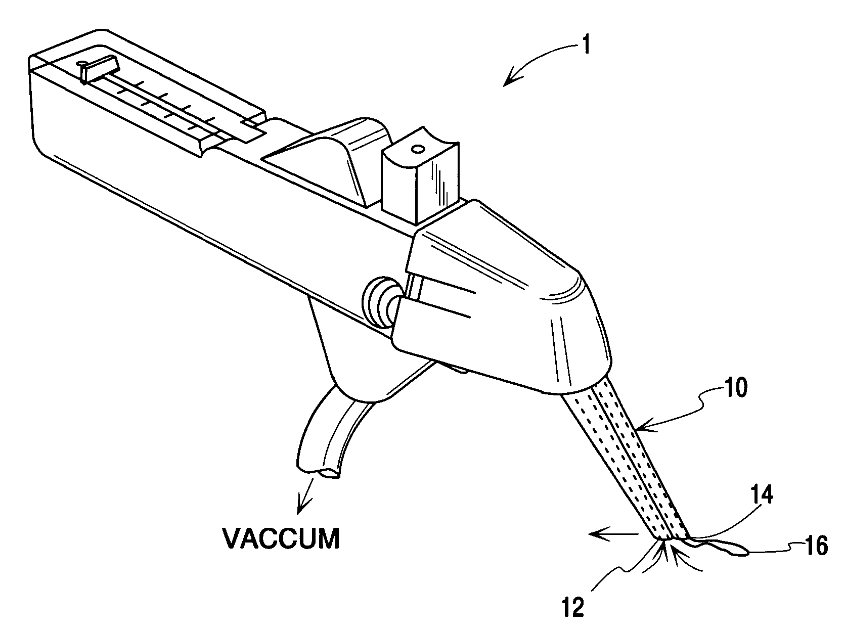
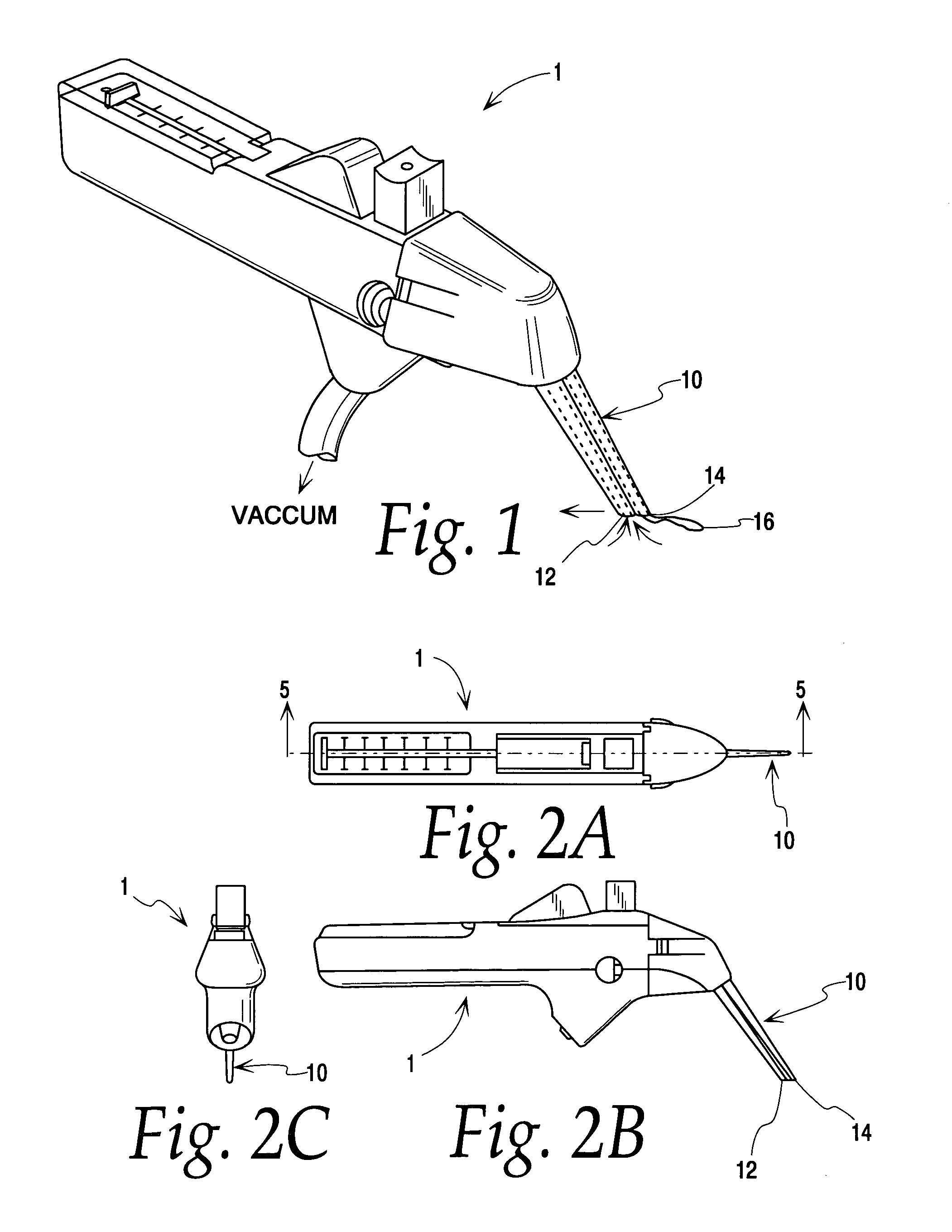
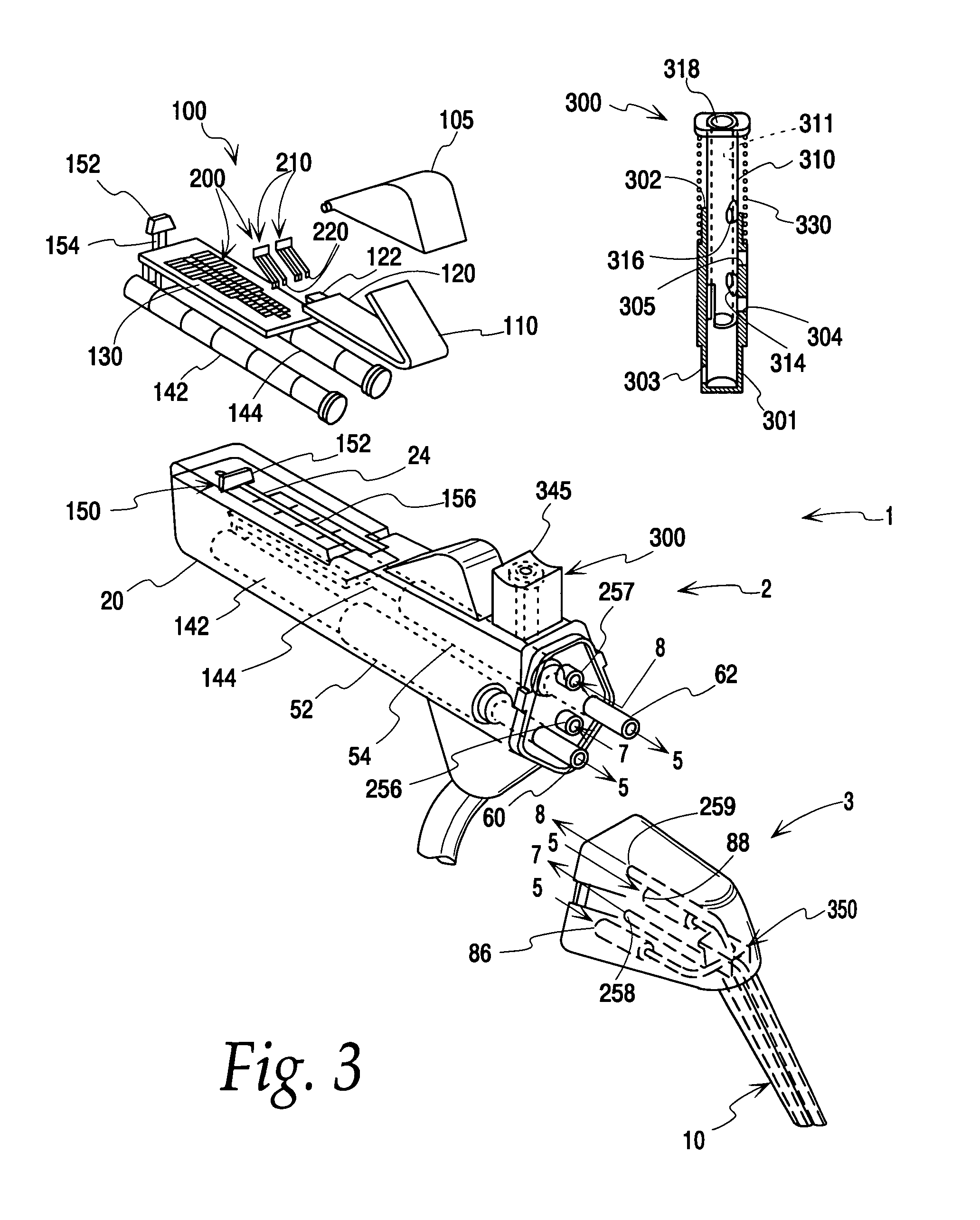
[0047]Detailed description of the suctioning device of the present invention is therefore provided as one part of an overall disclosure of the preferred mode of operation in a combination medical fluid applicator device having several assemblies and sub-assemblies described. FIGS. 1–2C provide various perspective views of the overall combination medical fluid applicator assembly. FIG. 3 provides an overview of the removably engageable supply device and applicator portions of the overall device, as well as the overall interior wor...


PUM


Abstract

A medical fluid suctioning device for selectively applying varied levels of suction pressure at a device-tissue interface includes a direct “trumpet”-type control mechanism in conjunction with a “venturi”-type control. A valve manifold is adapted to couple a vent pathway and a suction pathway simultaneously to the vacuum conduit adapted for connection to a vacuum source. The amount of resistance to flow due to vacuum pressure is adjusted simultaneously in both the vent pathway and the suction pathway in order to achieve controlled, selected levels of suction. Similarly shaped valve apertures are provided in inverse and reciprocal orientation along an axis of motion of a valve manifold. The apertures translate across ports to the suction and venting pathways simultaneously to vary applied suction to those pathways inversely. The shaped valve apertures preferably have diminished elliptical shapes having an elongate axis with an increasing cross-sectional area going from a transverse short axis to a transverse wide axis along the axis of motion of the valve manifold. The diminished elliptical shapes are inversely oriented relative to each other as regards the positioning of their wide and short transverse axis along the axis of motion.

Description

CROSS REFERENCE TO A RELATED APPLICATION[0001]This application is a continuation of patent application Ser. No. 09 / 421,353 filed Oct. 25, 1999 now U.S. Pat. No. 6,471,667 which is a continuation of patent application Ser. No. 08 / 839,614, filed Apr. 14, 1997 and entitled “MEDICAL SUCTIONING APPARATUS AND METHODS OF USE,” now U.S. Pat. No. 5,971,956, and a division of patent application Ser. No. 08 / 838,078 filed Apr. 14, 1997 now U.S. Pat. No. 6,331,172 and entitled “APPLICATOR FOR DISPENSING MEASURED QUANTITIES WITH USE OF CONTROLLED SUCTION” the disclosures of which applications are hereby incorporated herein by reference thereto.TECHNICAL FIELD[0002]The invention is a medical device which provides for controlled levels of applied suction at a device-tissue interface. More specifically, the invention is a medical fluid suctioning device which is combined with a dispensing assembly in an overall tissue adhesive applicator which selectively provides controlled levels of suction force ...

Claims


Application Information

Patent Timeline
Patent Type & Authority Patents(United States)
IPC IPC(8): A61M31/00A61B17/00A61B17/11A61M1/00A61M35/00
CPCA61B17/00491A61M1/0047A61M1/0043A61B2017/00495A61M1/0064Y10T137/86815A61M1/7413A61M1/7411A61M1/774
Inventor EPSTEIN, GORDAN HOWARD
Owner BAXTER INT INC
Learn More