Image forming apparatus and density detection pattern forming method therein

Active Publication Date: 2006-04-11
CANON KK
View PDF8 Cites 4 Cited by
  • Summary
  • Abstract
  • Description
  • Claims
  • Application Information

AI Technical Summary

Benefits of technology

[0015]The present invention has been made in consideration of the above situation, and has as its feature to accurately detect the density without any influen

Problems solved by technology

This is because, if the density of each density patch is close to the maximum density in detecting a so-called solid image for forming a density patch, the change width of an output of the sensor upon a change in toner amount becomes narrow, failing to obtain a satisfactory detection precision.
When the numb

Method used


Image

  • Image forming apparatus and density detection pattern forming method therein
  • Image forming apparatus and density detection pattern forming method therein
  • Image forming apparatus and density detection pattern forming method therein

Examples


Example

[First Embodiment]

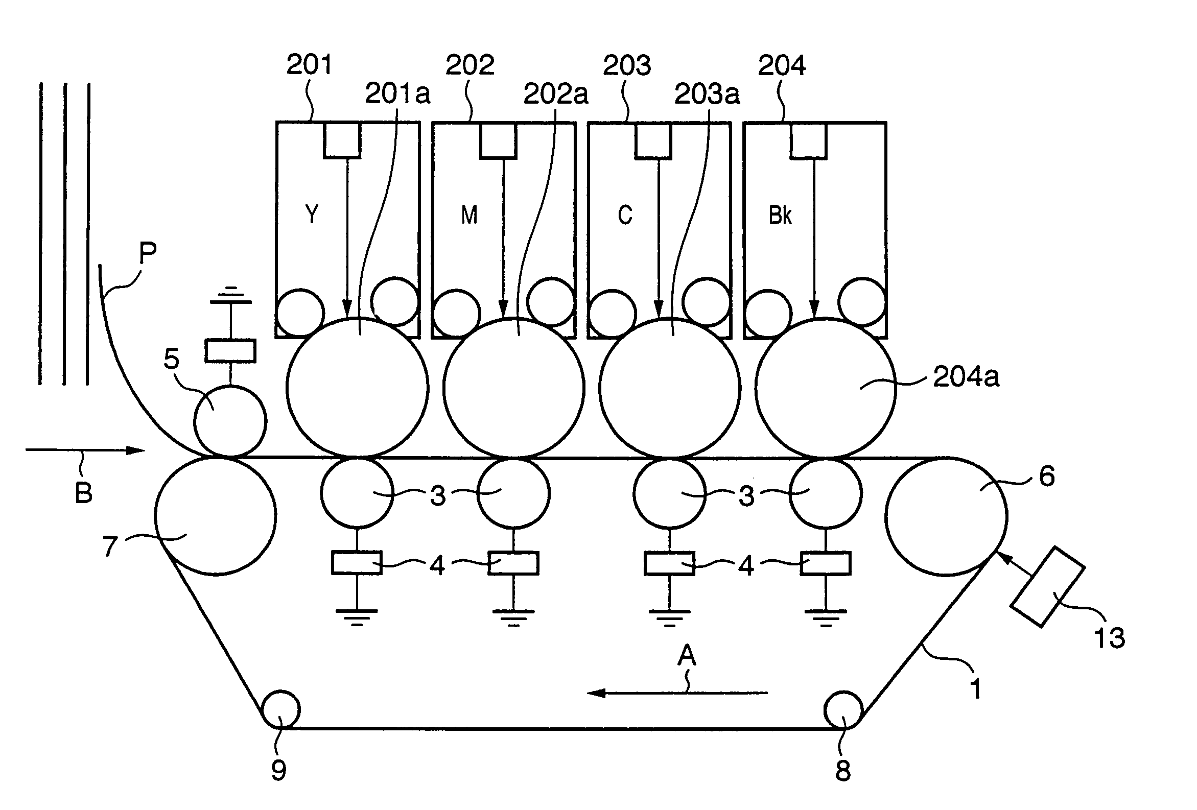
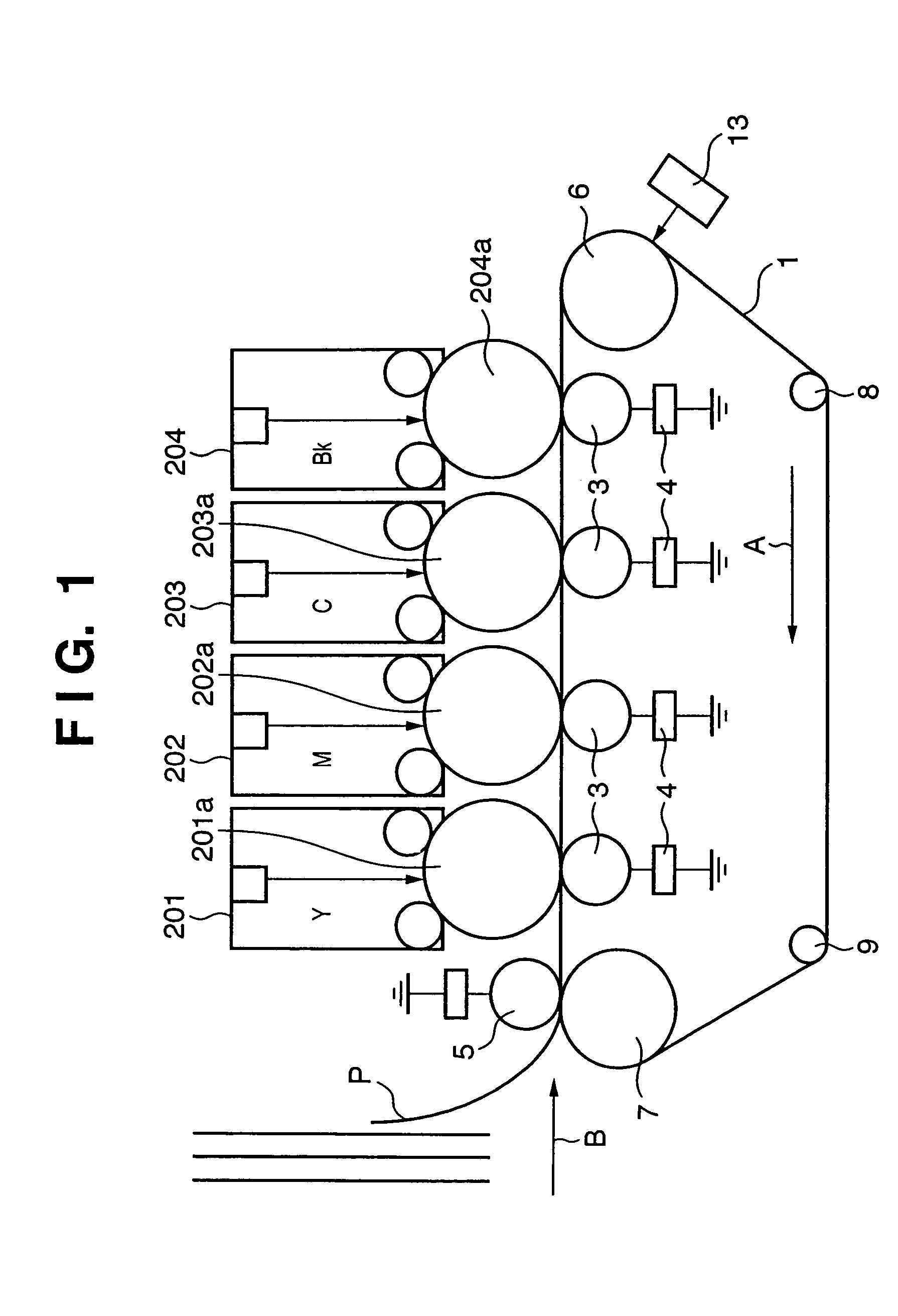
[0034]FIG. 1 depicts a conceptual view for explaining the in-line arrangement of an electrophotographic image forming apparatus (laser beam printer) according to the first embodiment of the present invention.

[0035]In FIG. 1, an electrostatic chuck / convey belt (to be referred to as an ETB hereinafter) 1 is looped by a driving roller 6, a facing chuck roller 7, and tension rollers 8 and 9, and rotates in a direction indicated by an arrow A. A process station (yellow) 201, process station (magenta) 202, process station (cyan) 203, and process station (black) 204 for different colors are aligned in a line on the outer surface of the ETB 1, as shown in FIG. 1. Photosensitive drums 201a to 204a in the respective process stations abut against transfer rollers 3 via the ETB 1. A chuck roller 5 is arranged on the upstream side of the process stations, and abuts against the facing chuck roller 7 via the ETB 1. When a transfer medium (print sheet) P passes through a nip forme...

Example

[Second Embodiment]

[0064]The second embodiment of the present invention will be described.

[0065]Also in the second embodiment, a photosensitive drum having a peripheral length of 90 mm is employed, and the length of one density patch is set to 10 mm. The number of density patches is 16 for one color. The hardware arrangement of a laser beam printer according to the second embodiment is the same as that according to the first embodiment, and a description thereof will be omitted.

[0066]In the second embodiment, the size of one density patch is set to an almost odd fraction ( 1 / 9 in the second embodiment) of the peripheral length of the photosensitive drum. Density patches are scatteredly formed at an interval.

[0067]FIG. 10 depicts a view for explaining a method of forming cyan density patches in the second embodiment.

[0068]In the second embodiment, as shown in FIG. 10, density patches are formed at an interval of 30 mm. Alternatively, the purpose of the present invention can also be a...


PUM


Abstract

In an image forming apparatus which forms an image on an image carrier, a predetermined density pattern is segmented into a plurality of blocks to generate the plurality of blocks. The density patterns of the plurality of generated blocks are controlled to be formed on the image carrier so as not to superpose the density patterns in two successive turns of the image carrier.

Description

FIELD OF THE INVENTION[0001]The present invention relates to an image forming apparatus using an electrophotographic process and a density pattern forming method in the image forming apparatus.BACKGROUND OF THE INVENTION[0002]Image forming methods in image forming apparatuses such as a printer apparatus are roughly classified into an electrophotographic method, thermal transfer method, and ink-jet method. Image forming apparatuses using the electrophotographic method are higher in speed, image quality, and quietness than those using other methods, and have recently become popular. Electrophotographic methods are further categorized into various methods. For example, in addition to a well-known multi-transfer method and intermediate transfer member method, there is proposed a multiple development method of overlapping Y, M, C, and K color images on the surface of a photosensitive body to form a full-color image, transferring the full-color image onto a print sheet at once, and thereb...

Claims


Application Information

Patent Timeline
IPC IPC(8): G03G15/00
CPCG03G15/5058G03G2215/0161
Inventor FUNATANI, KAZUHIRO
Owner CANON KK
Why Eureka
Try Eureka