Convergence technique for model-based optical and process correction

a convergence technique and model-based technology, applied in the field of verification and correction techniques, can solve the problems of limited capability of rule-based opc, line-width variation, and affecting the yield of silicon

Inactive Publication Date: 2006-04-11
SIEMENS PROD LIFECYCLE MANAGEMENT SOFTWARE INC
View PDF27 Cites 54 Cited by
  • Summary
  • Abstract
  • Description
  • Claims
  • Application Information

AI Technical Summary

Benefits of technology

[0008]Rule-based OPC operations are performed in an integrated device design layout that results in one or more modified reticle layout. Model-based correction is performed on the modified reticle layouts.
[0009]In one embodiment, for model-based correction, a simulated layer of an integrated device to be manufactured is compared to a target layout representing a desired integrated device layer. The simulation is based on layouts of multiple reticles corresponding to the layer of the integrated device. An edge placement error is determined for one or more layout f

Problems solved by technology

However, with deep sub-micron processes, silicon yield is affected by several factors including reticle/mask pattern fidelity, optical proximity effects, and diffusion and loading effects during resist and etch processing.
Typical problems include line-width variations that depend on local pattern density and

Method used


Image

  • Convergence technique for model-based optical and process correction
  • Convergence technique for model-based optical and process correction
  • Convergence technique for model-based optical and process correction

Examples


Embodiment Construction

[0026]Methods and apparatuses for integrated device design correction using segment correspondences are described. In the following description, for purposes of explanation, numerous specific details are set forth in order to provide a thorough understanding of the invention. It will be apparent, however, to one skilled in the art that the invention can be practiced without these specific details. In other instances, structures and devices are shown in block diagram form in order to avoid obscuring the invention.

[0027]Reference in the specification to “one embodiment” or “an embodiment” means that a particular feature, structure, or characteristic described in connection with the embodiment is included in at least one embodiment of the invention. The appearances of the phrase “in one embodiment” in various places in the specification are not necessarily all referring to the same embodiment.

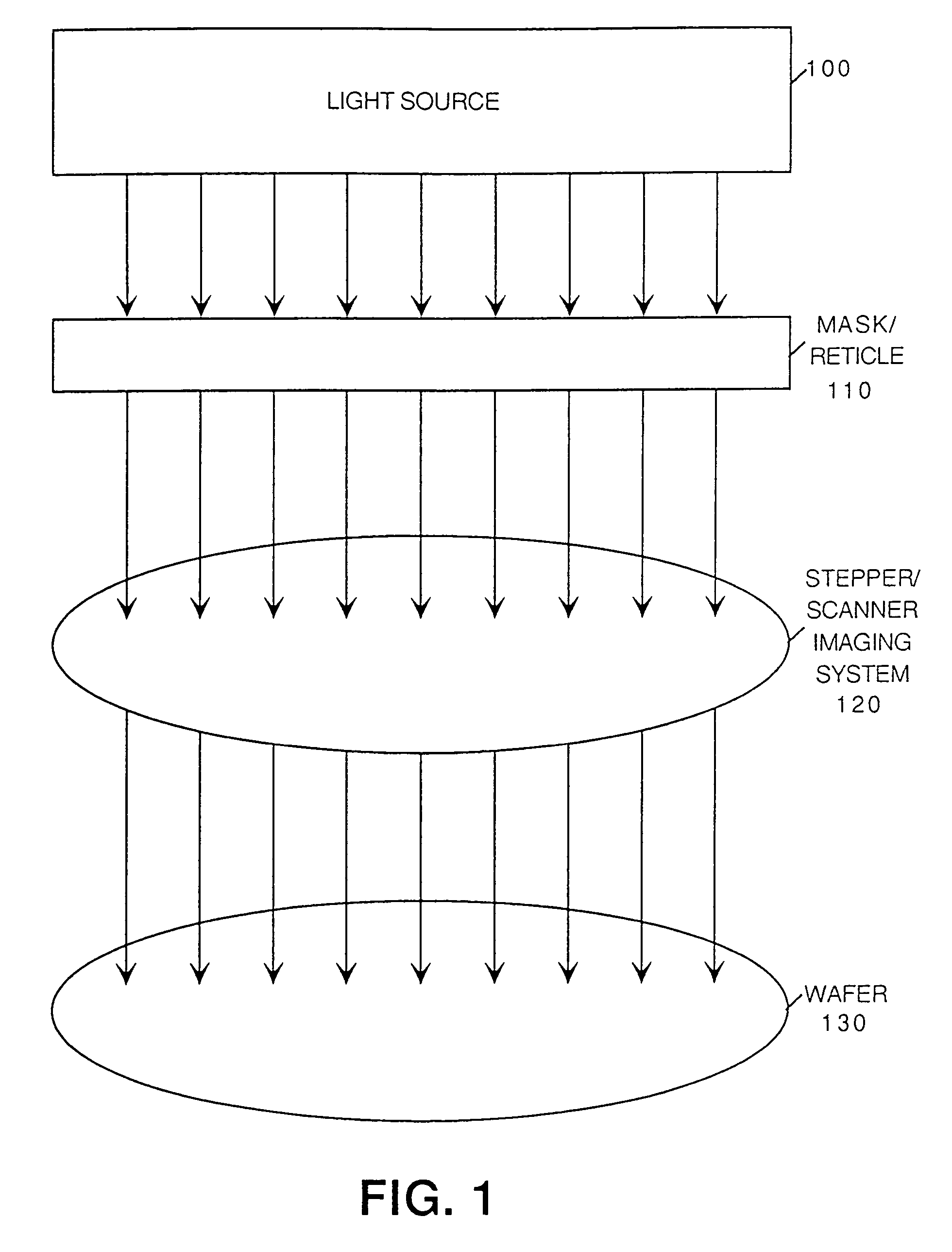
[0028]Methods and apparatuses are described herein with respect to integrated circuit manufact...


PUM


Abstract

Layout correction is accomplished using a forward mapping technique. Forward mapping refers to mapping of fragments from a reticle layout to a target layout, while backward mapping refers to mapping of fragments from the target layout to the reticle layout. Forward mapping provides a technique for making an unambiguous mapping for each reticle fragment to a corresponding target layout fragment. The mapping does not necessarily provide a one-to-one correspondence between reticle fragments and target layout fragments. That is, multiple reticle layout fragments can map to a single target layout fragment. An edge placement error for the target layout fragments is used to make positioning corrections for the corresponding reticle fragment(s). Edge placement error can be determined, for example, with a simulation process that simulates a manufacturing process using the reticles.

Description

[0001]This U.S. patent application is a continuation of U.S. patent application Ser. No. 09 / 613,214, filed Jul. 10, 2000 now U.S. Pat. No. 6,430,737.[0002]The present U.S. Patent application is related to U.S. patent application Ser. No. 09 / 613,213, filed Jul. 10, 2000, entitled “INTEGRATED CIRCUIT DESIGN CORRECTION USING FRAGMENT CORRESPONDENCE.”FIELD OF THE INVENTION[0003]The invention relates to integrated device design. More particularly, the invention relates to verification and correction techniques that can be used in an integrated device design and manufacturing process.BACKGROUND OF THE INVENTION[0004]As integrated circuits (ICs) become more dense, the widths of lines and components, as well as the separation between lines becomes increasingly smaller. Currently, deep sub-micron (<0.25 μm) processes are being used. However, with deep sub-micron processes, silicon yield is affected by several factors including reticle / mask pattern fidelity, optical proximity effects, and ...

Claims


Application Information

Patent Timeline
IPC IPC(8): G06F17/50G03F1/00G03F1/36H01L21/027
CPCG03F1/144G06F17/5081G03F1/36G03F1/70G06F30/398
Inventor COBB, NICOLAS BAILEYSAHOURIA, EMILE
Owner SIEMENS PROD LIFECYCLE MANAGEMENT SOFTWARE INC
Why Eureka
Try Eureka