Method and apparatus for positioning an end of a push rod of a brake actuator

Inactive Publication Date: 2006-04-18
HALDEX BRAKE
View PDF19 Cites 4 Cited by
  • Summary
  • Abstract
  • Description
  • Claims
  • Application Information

AI Technical Summary

Benefits of technology

[0011]It is another object of the invention to provide a push rod and ball end assembly that maintains its accurately determined overall length over prolonged use of the br

Problems solved by technology

The considerable inertial mass of these heavy-duty vehicles in combination with the high speeds at which they travel often requires a braking system which responds rapidly with substantial braking power.
If the overall length is too long, the brakes may be applied continuously or when a user does not wish the vehicle to be braked, which may cause premature wear on the brakes.
Because of the importance of the overall length, using shims to variably adjust the overall length may negatively affect accurate determinations of this length, which may possibly affect braking performance.
In some instances, especially where an accurate determination of the overall length is desired, the resulting tolerance stack up may be larger than the acceptable tolerance range for the overall length, resulting i

Method used


Image

  • Method and apparatus for positioning an end of a push rod of a brake actuator
  • Method and apparatus for positioning an end of a push rod of a brake actuator
  • Method and apparatus for positioning an end of a push rod of a brake actuator

Examples


Example

DETAILED DESCRIPTION OF THE DRAWINGS

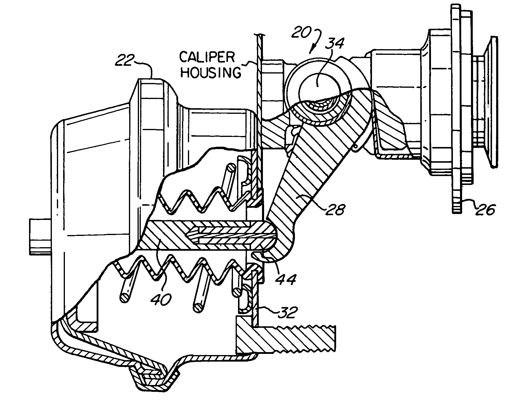
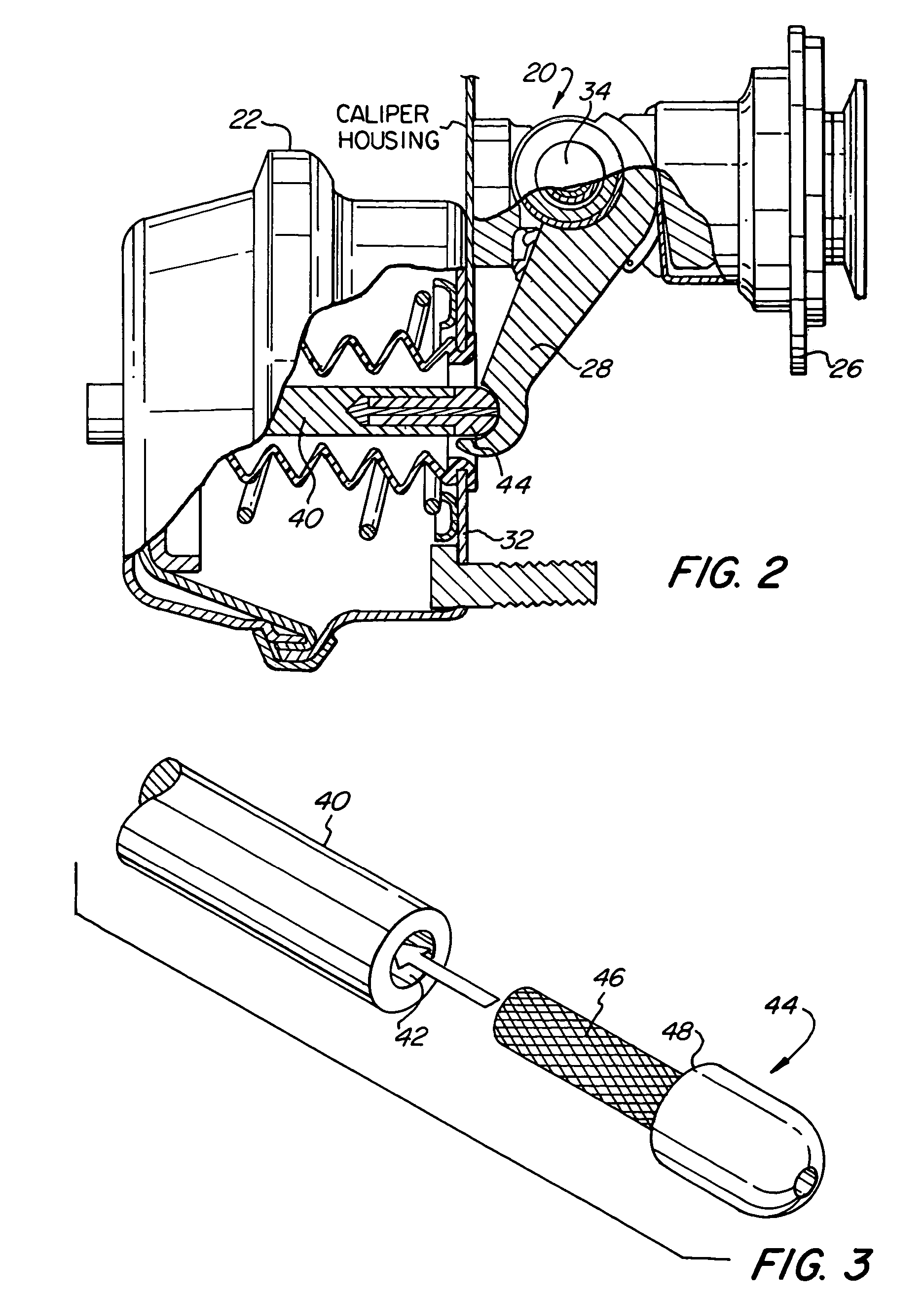
[0032]FIG. 2 depicts a brake system 20, including a brake actuator 22, caliper 26 for grasping a disc brake (shown in FIG. 1) during braking, push rod 40, ball end 44, and arm 28 for receiving ball end 44 and transferring the force from ball end 44 to caliper 26. Braking is applied by a vehicle operator pressing on a brake pedal, which causes actuator 22 to push upon push rod 40, which in turn extends away from a mounting face surface 32 and pushes upon ball end 44, which in turn pushes upon arm 28. As a result, arm 28 rotates about pivot 34 and causes caliper 26 to grasp the disc brake, which brakes the axle and wheels. As once can see, the overall length of push rod 40 and ball end 44 relative to mounting face surface 32 affects the rotation of pivot 34 and, therefore, braking. The overall length, represented by dimension L, is shown in FIG. 4b.

[0033]FIG. 3 more particularly depicts push rod 40 and ball end 44. As shown, ball end 44 is inserted...


PUM


Abstract

The invention relates to a method and apparatus for positioning components of a brake system, which includes a push rod, a ball end coupled to the push rod, and a force transfer member placed between the push rod and the ball end. The force transfer member has both a flowable property and a solidifying property, whereby the force transfer member is flowable when being placed between the push rod and ball end and, after a passage of time, the force transfer member solidifies.

Description

CROSS-REFERENCE TO RELATED APPLICATIONS[0001]This application is a divisional of U.S. patent application Ser. No. 10 / 288,122, filed Nov. 5, 2002, now issued as U.S. Pat. No. 6,755,233.FIELD OF THE INVENTION[0002]The invention relates to braking systems and, more particularly, a method and apparatus for positioning an end of a push rod of a brake actuator.BACKGROUND OF THE INVENTION[0003]Braking systems, such as air brake systems, have generally been used to control movement of motor vehicles in a safe and effective manner. In particular, air brakes are commonly used on commercial vehicles such as trucks, trailers, and buses, which typically have large gross vehicle weights. The considerable inertial mass of these heavy-duty vehicles in combination with the high speeds at which they travel often requires a braking system which responds rapidly with substantial braking power. One system component which may be instrumental in the operation of air brake systems is the brake actuator. Th...

Claims


Application Information

Patent Timeline
IPC IPC(8): F16D55/08B60T7/10B60T17/08F16D65/14F16D65/18F16D65/28
CPCB60T17/081B60T17/088F16D65/18F16D65/28F16D2125/70F16D2121/02F16D2125/32B60T7/10
Inventor FISHER, ALBERT D.
Owner HALDEX BRAKE
Why Eureka
Try Eureka