Slidable boring tool with fine adjustment

a sliding, boring tool technology, applied in the field of boring tools, can solve the problems of reducing the speed and affecting the speed and economy of the boring tool, and the clamping force of the boring tool is not maintained during the adjustment, so as to achieve the effect of reducing the labor intensity of the adjustment method, reducing the speed and economy, and slowing down the speed and economy

Inactive Publication Date: 2006-04-18
CARDEMON INC D B A CAR TEC +1
View PDF256 Cites 19 Cited by
  • Summary
  • Abstract
  • Description
  • Claims
  • Application Information

AI Technical Summary

Problems solved by technology

However, many boring tools require manual adjustment by the machine operator.
Thus, the clamping force holding the cutting tool on the boring tool is not maintained during adjustment and the tool is reclamped after adjustment.
This slow, inflexible, labor-intensive adjustment method detracts from the speed and economy of the CNC machine by requiring the operator to stop the operation of the CNC machine during the period of adjustment.

Method used


Image

  • Slidable boring tool with fine adjustment
  • Slidable boring tool with fine adjustment
  • Slidable boring tool with fine adjustment

Examples


Embodiment Construction

[0174]For the purposes of promoting an understanding of the principles of the invention, reference will now be made to the embodiments illustrated in the drawings and specific language will be used to describe the same. It will nevertheless be understood that no limitation of the scope of the invention is thereby intended, such alterations and further modifications in the illustrated devices, and such further applications of the principles of the invention as illustrated therein being contemplated as would normally occur to one skilled in the art to which the invention relates.

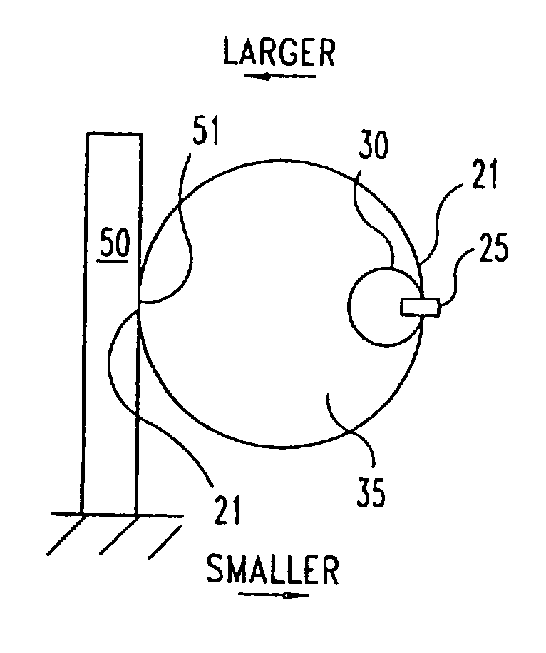
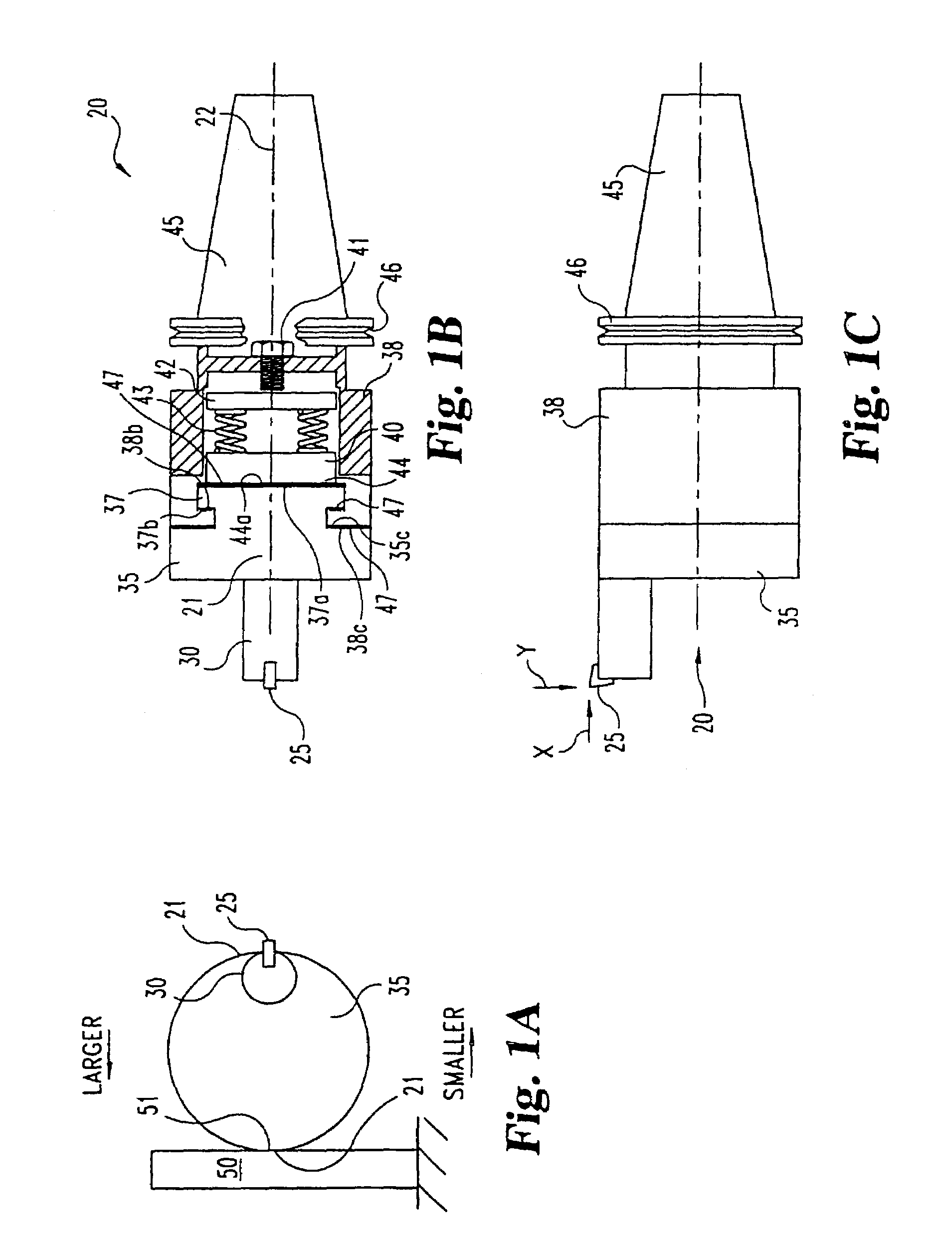
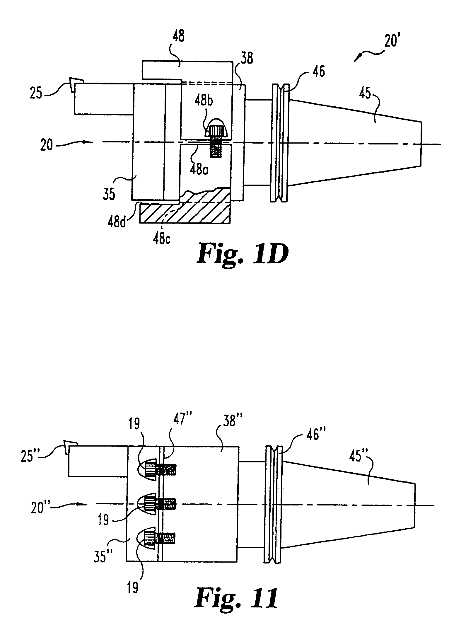
[0175]The present invention relates both to apparatus and method by which the operator can adjust the sideways location of a cutting tool used in a machining operation; for example, a cutting tool used for boring holes with a CNC boring machine. According to one embodiment of this invention, the cutting tool or cutting tool holder is coupled to the machine coupling element, and can be moved relative to the cou...


PUM

PropertyMeasurementUnit
angleaaaaaaaaaa
anglesaaaaaaaaaa
anglesaaaaaaaaaa

Abstract

Methods and apparatus for fine adjustment of the position of the cutting tool. In one embodiment, a boring tool includes a coupling member driven by a CNC boring machine, a cutting tool which is slidably coupled to the coupling member, and a slidable adjustment member. A frictional force resists sliding movement of the cutting tool. The frictional force is sufficient to retain the position of the cutting tool during machining operations. However, the frictional force is insufficient to resist an adjusting force applied by the adjustment member. Sliding motion of the adjustment, either by pulling or pushing it, results in movement of the cutting tool. In one embodiment, the cutting tool and the adjustment member are slidable in different directions. In another embodiment, the boring tool is adapted and configured to convert a first, greater amount of movement by the adjustment member to a second, lesser amount of movement by the cutting tool.

Description

[0001]This application claims the benefit of priority to U.S. Provisional patent application No. 60 / 375,320, filed Apr. 25, 2002. This application is a continuation-in-part of and claims priority to U.S. patent application Ser. No. 10 / 023,243 filed Dec. 18, 2001 now U.S. Pat. No. 6,705,184. That application claims the benefit of priority to U.S. Provisional Applications Ser. No. 60 / 256,371, filed Dec. 18, 2000; and Ser. No. 60 / 270,723, filed Feb. 22, 2001. All of these patent applications are incorporated herein by reference.FIELD OF THE INVENTION[0002]This invention concerns an apparatus for a tool used when performing a machining operation, and more specifically to a boring tool used with a Computer Numerically Controlled (CNC) boring machine.BACKGROUND OF THE INVENTION[0003]Many products, such as automotive transmission housing and engine blocks, include precision bored holes. These holes are bored by cutting tools supported by a boring tool which is driven by a boring machine. I...

Claims


Application Information

Patent Timeline
Patent Type & Authority Patents(United States)
IPC IPC(8): B23B35/00B23B29/034
CPCB23B29/03403B23B29/03457B23B2270/08Y10T408/8593Y10T82/10Y10T408/8588Y10T82/125Y10T408/76Y10T408/03
Inventor CARDEMON, RICHARD A.BAKER, JOSEPH
Owner CARDEMON INC D B A CAR TEC
Why Eureka
Try Eureka