Weight training machine for exercising the upper chest muscles

Active Publication Date: 2006-04-18
NAUTILUS INC
View PDF16 Cites 20 Cited by
  • Summary
  • Abstract
  • Description
  • Claims
  • Application Information

AI Technical Summary

Benefits of technology

[0007]The present invention is directed to a pec fly machine that can enable a user to exercise the lower portion of the pectoralis major intensely. In one embodiment, a machine of the present invention includes: a frame configured to rest on an underlying surface; a seat mounted to the frame; a backrest mounted to the frame above the seat, the seat and backrest being configured to receive a seated user; a pair of movement arm units pivotally interconnected with the frame and movable about respective generally parallel first and second axes of rotation; and a resistance system connected with the movement arm units. Each of the movement arms is configured to engage at least one of the elbows, forearms and hands o

Problems solved by technology

Conventionally, movement of the mechanical member is resisted in some fashion (often by weights) to render the movement more difficult and thereby intensify the exercise.
As a result, the plane of motion of the typical pec fly machine described above de

Method used


Image

  • Weight training machine for exercising the upper chest muscles
  • Weight training machine for exercising the upper chest muscles
  • Weight training machine for exercising the upper chest muscles

Examples


Example

[0014]The present invention will now be described more fully hereinafter, in which preferred embodiments of the invention are shown. This invention may, however, be embodied in different forms and should not be construed as limited to the embodiments set forth herein. Rather, these embodiments are provided so that this disclosure will be thorough and complete, and will fully convey the scope of the invention to those skilled in the art. In the drawings, like numbers refer to like elements throughout. Thicknesses and dimensions of some components may be exaggerated for clarity.

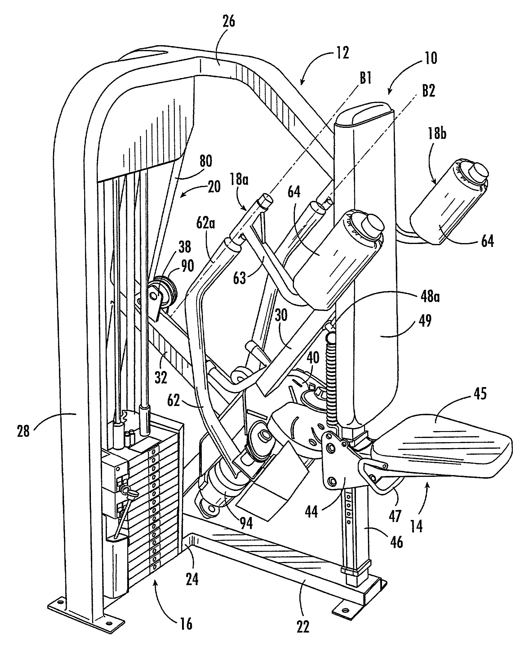
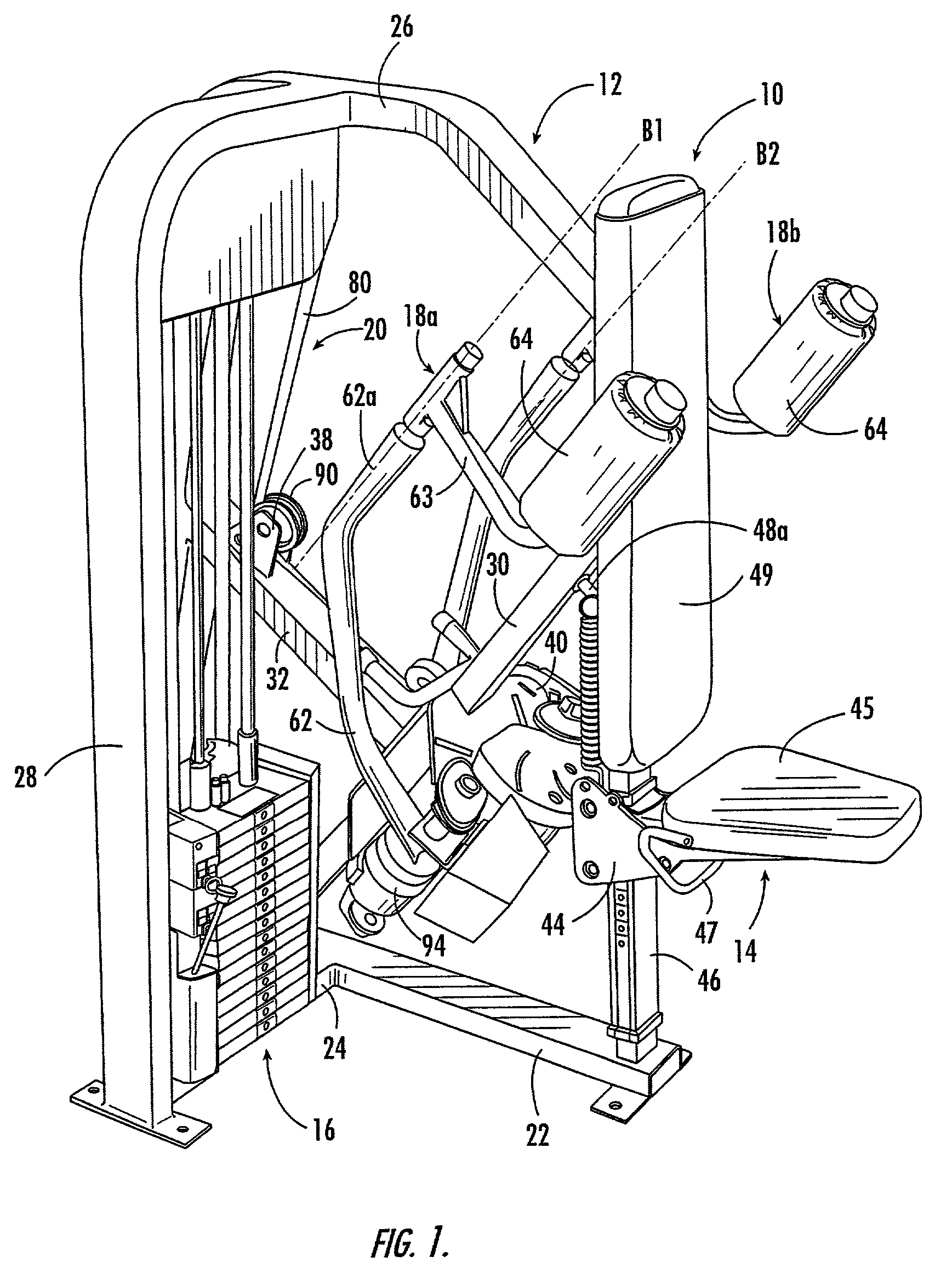
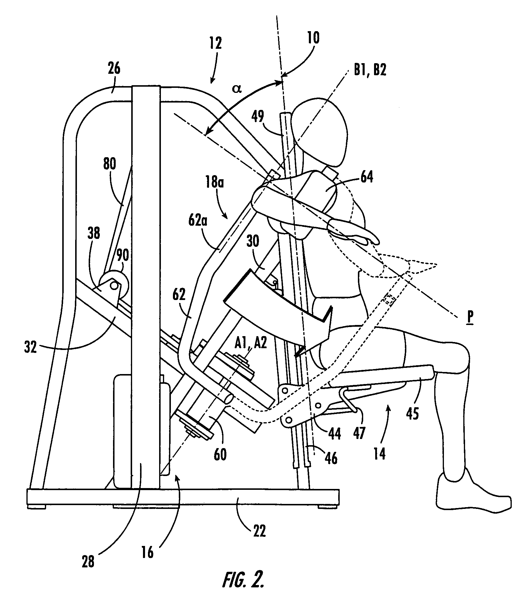
[0015]Referring to the figures, an exercise machine, designated broadly at 10, is illustrated in FIGS. 1–5. The machine 10 includes a frame 12, a seat assembly 14, a weight stack 16, a pair of movement arm units 18a, 18b, and a belt / pulley system 20. These components are described in detail below.

[0016]Referring to FIGS. 1–3, the frame 12 includes a longitudinal base member 22, a transverse base member 24 that ...


PUM


Abstract

An exercise machine includes: a frame configured to rest on an underlying surface; a seat mounted to the frame; a backrest mounted to the frame above the seat, the seat and backrest being configured to receive a seated user; a pair of movement arm units pivotally interconnected with the frame and movable about respective generally parallel first and second axes of rotation; and a resistance system connected with the movement arm units. Each of the movement arms is configured to engage at least one of the elbows, forearms and hands of the user and is movable, within a range of motion plane that is generally normal to the first and second axes of rotation, between an extended position and a flexed position. The range of motion plane forms an angle of between about 30 and 80 degrees with the backrest.

Description


Claims


Application Information

Patent Timeline
IPC IPC(8): A63B21/062A63B23/12
CPCA63B23/1245A63B23/1254A63B21/062A63B2225/093A63B2208/0233A63B21/0628A63B23/03533A63B23/1272A63B21/4047
Inventor VUURMANS, HENRIWEBB, GREGORY M.
Owner NAUTILUS INC
Why Eureka
Try Eureka