Method of eliminating fume for regenerated catalyst

A technology for regenerating catalysts and catalysts, applied in chemical instruments and methods, catalyst regeneration/reactivation, physical/chemical process catalysts, etc., can solve problems affecting gas-solid contact efficiency, etc., achieve easy implementation, and prevent the formation of flow dead zones , the effect of simple structure

Inactive Publication Date: 2005-11-09
CHINA PETROLEUM & CHEM CORP +1
View PDF5 Cites 2 Cited by
  • Summary
  • Abstract
  • Description
  • Claims
  • Application Information

AI Technical Summary

Problems solved by technology

The stripper is a baffle-type stripper, and the gas-solid flow is restricted at the angle between the baffle and the side wall and under the herringbone baffle, which affects the gas-solid contact efficiency.

Method used


Image

  • Method of eliminating fume for regenerated catalyst
  • Method of eliminating fume for regenerated catalyst
  • Method of eliminating fume for regenerated catalyst

Examples


Embodiment

[0036] This example shows that the amount of smoke carried by the regeneration agent can be significantly reduced by adopting the method provided by the present invention.

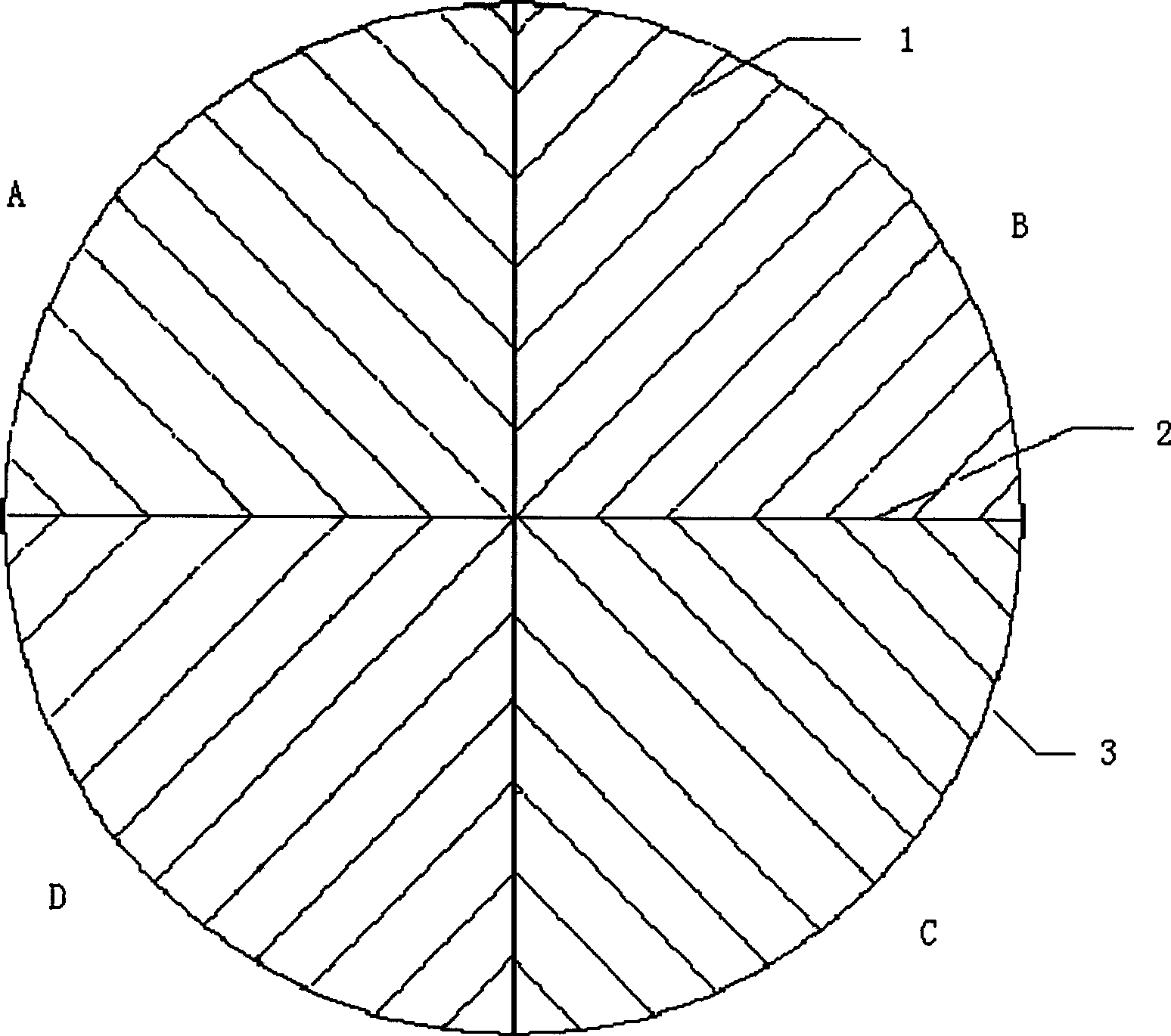
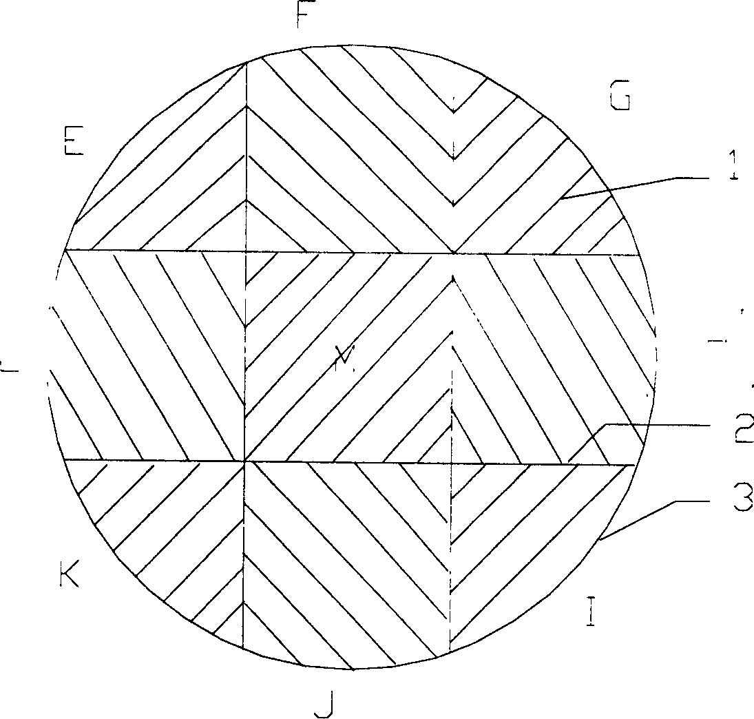
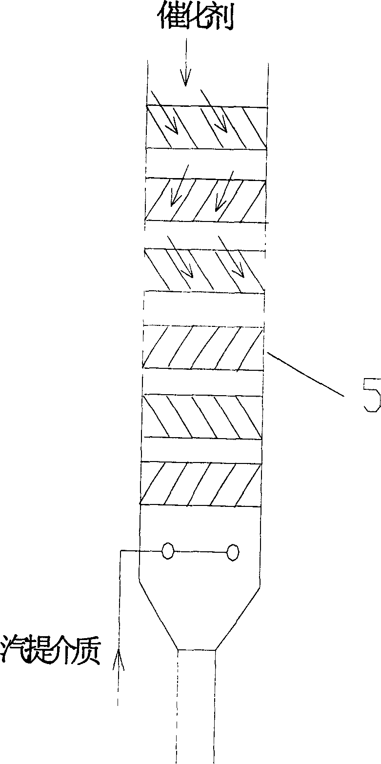
[0037] The medium-sized riser catalytic cracking unit is modified, and a regenerative flue gas stripper is added downstream of the regenerator. Adopt internal member described in the present invention, the structure of internal member is as figure 1 shown. The inner diameter of the regenerative flue gas stripper is 500mm, and four internal components are arranged in the stripper. The height of the inner member is 100mm, and each inner member is divided into 4 areas. The angle between the baffle piece and the horizontal direction in each area is 22.5°, and each inner member is rotated horizontally by 45°C along the axial direction from top to bottom. The interval between every two layers of internal components is 50mm.

[0038] The main properties of the raw oil used in the test are shown in Table 1. Th...


PUM


Abstract

A method of removing smoke from a regenerative catalyst comprise, a regenerative catalyst is added into a steam stripping machine for regenerative smoke and brought contact with steam stripping medium, smoke there of is removed, after steam stripping, the regenerative catalyst leaves the steam stripping machine. A tray inner member with four or more floors is horizontally in the steam-stripping machine. The regenerative catalyst and the steam stripping medium would change directions of each other when flowing each floor. By the invention, smoke of regenerative catalysts would be reduced, impurities in hydrocarbon product will be lowered down.

Description

technical field [0001] The present invention belongs to the catalytic cracking method of petroleum hydrocarbons in the absence of hydrogen, more specifically, a method for degassing a regenerated catalyst. Background technique [0002] In the conventional catalytic cracking process, the raw oil is atomized with water vapor and sprayed into the riser, where it contacts the high-temperature catalyst (600-700°C) from the regenerator, and then vaporizes and reacts. The residence time of oil and gas in the riser is very short, generally only a few seconds. The reaction product is separated from the entrained catalyst by the cyclone separator and then leaves the reactor to the fractionation tower. The catalyst with coke (called spent catalyst) falls into the stripping section below from the settler. The stripping section is equipped with multi-layer herringbone baffles and superheated steam is introduced at the bottom, and the oil gas adsorbed on the catalyst to be used and the ...

Claims


Application Information

Patent Timeline
Patent Type & Authority Patents(China)
IPC IPC(8): B01J8/08B01J38/06C10G35/10
Inventor 朱丙田侯拴弟龙军许克家李松年钟孝湘武雪峰汪燮卿
Owner CHINA PETROLEUM & CHEM CORP
Why Eureka
Try Eureka