Stirring-type magnetic separation device

A magnetic separation device, a magnetic device technology, applied in the direction of magnetic separation, solid separation, grain processing, etc., can solve the problems of affecting the adsorption effect, magnetic separation effect, mutual hooking, etc., and achieve the effect of convenient stirring magnetic separation

Inactive Publication Date: 2019-06-25
山东上元再生资源有限公司
View PDF5 Cites 7 Cited by
  • Summary
  • Abstract
  • Description
  • Claims
  • Application Information

AI Technical Summary

Problems solved by technology

Since there is a distance between the conveyor belt with magnetic separation and the main conveyor belt below, if the distance is too large, it will affect the adsorption effect, if the distance is small, it will hinder the transportation of materials, and the shape of the iron and steel distribution is irregular, there will be interaction The occurrence of hooking and difficult separation will further affect the magnetic separation

Method used


Image

  • Stirring-type magnetic separation device
  • Stirring-type magnetic separation device
  • Stirring-type magnetic separation device

Examples


Embodiment 1

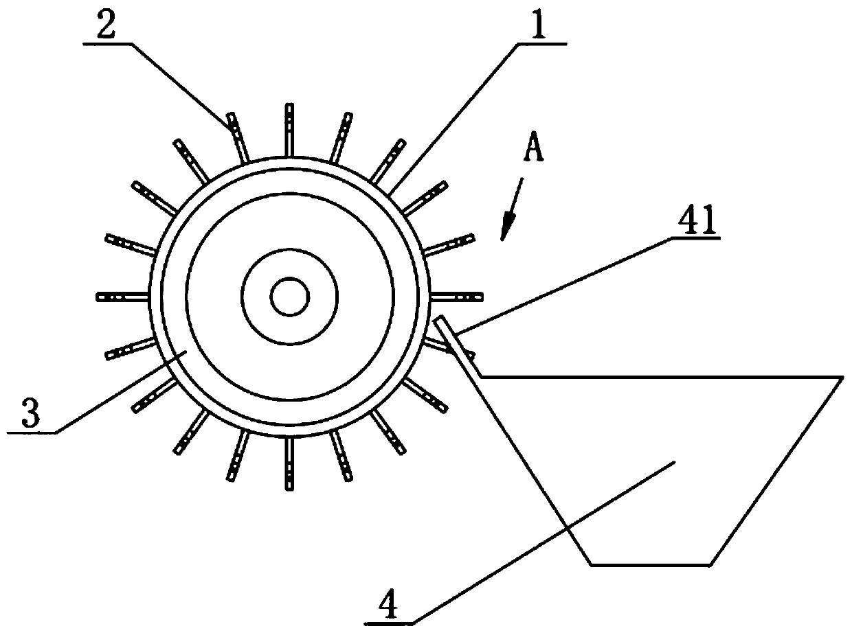
[0032] Such as figure 1 As shown, this embodiment provides an agitating magnetic separation device, which includes a rotatable carrier 1 and magnetically conductive teeth 2 arranged on the surface of the carrier 1 . The carrier 1 is a roller, and the magnetically conductive teeth 2 are distributed along the circumference on the surface of the carrier 1 . The magnetically permeable tooth 2 is made of magnetically permeable material and is shaped like a rod. A magnetic device 3 that rotates with the carrier 1 is disposed inside the carrier 1 , and the magnetic device 3 is a permanent magnet.

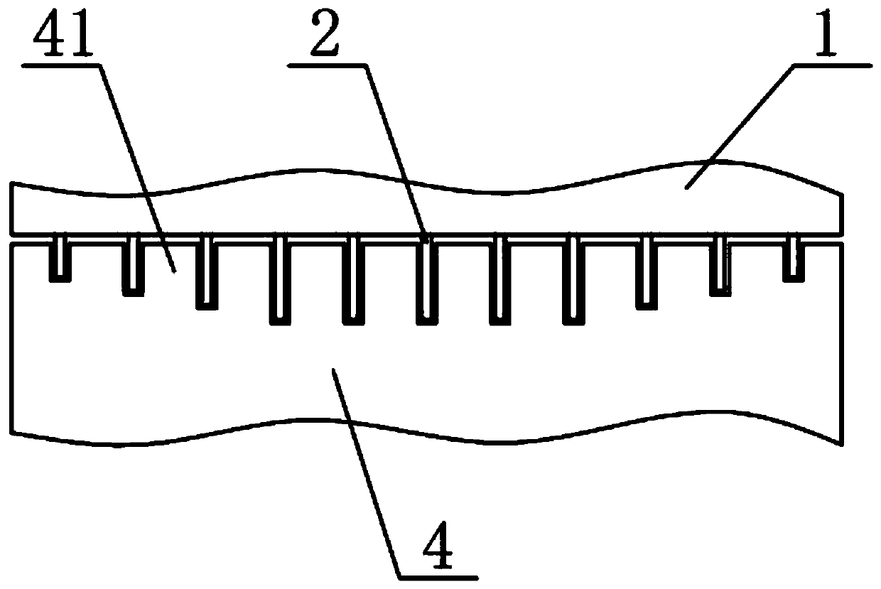
[0033] Such as figure 1 figure 2 As shown, the output side of the carrier 1 is provided with a receiving hopper 4 , and one side of the receiving hopper 4 is arranged close to the carrier 1 , and there is a small gap between it and the carrier 1 . The receiving hopper 4 is provided with separating teeth 41, and the spacing of the separating teeth 41 matches the size and spacing of the...

Embodiment 3

[0039] Such as Figure 5 As shown, in this embodiment, the carrier 1 includes a magnetic separation conveyor belt 11 and a guide roller 12, and the magnetic separation conveyor belt 11 is arranged outside the guide roller 12 to form a conveyor belt structure. The magnetically conductive teeth 2 are arranged outside the magnetic separation conveyor belt 11 . Other parts of this embodiment are basically the same as those of Embodiment 1.

Embodiment 4

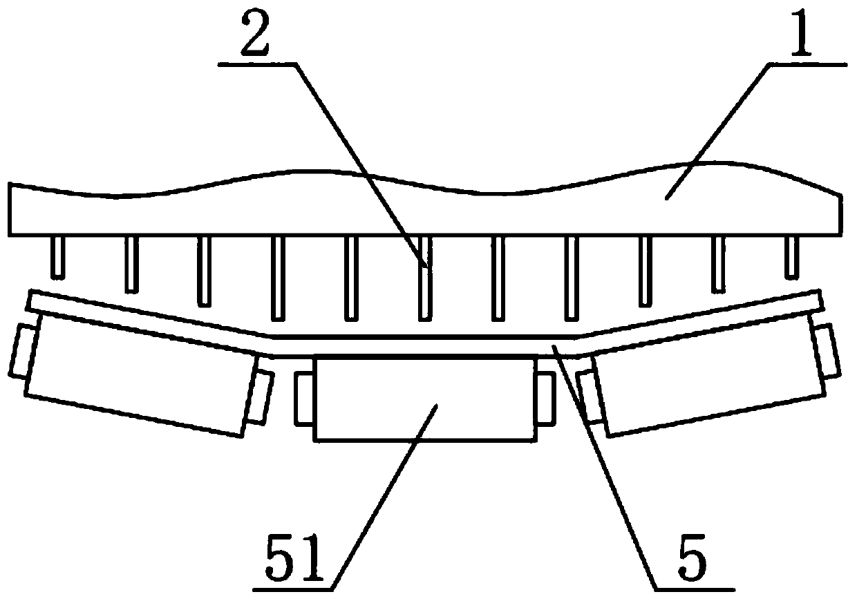
[0041] Such as image 3 Figure 6 As shown, this embodiment provides an agitating magnetic separation machine, including the magnetic separation device in Embodiment 1 and the main conveyor belt 5 , and the magnetic separation device is arranged above the main conveyor belt 5 . The main conveyer belt 5 passes through the setting of the supporting roller 51, and the center is concave, forming such as image 3 The shape shown is compatible with the length of the magnetic permeable tooth 2 . The direction of movement of the upper side of the main conveyor 5 is opposite to the direction of movement of the lower side of the carrier 1 .

[0042] Below the main conveyor belt 5, an impact device 6 is arranged at the front end of the magnetic separation device. The impact device 6 is a slider crank mechanism, including a rotatable crank 61, and a connecting rod 62 and a crossbeam 63. The body of the magnetic separator is vertically slidably connected. The crank 61 can drive the con...


PUM


Abstract

The invention relates to the field of iron and steel waste recycling equipment, in particular to a stirring-type magnetic separation device which can effectively improve the magnetic separation efficiency of dry magnetic separation and does not affect material transportation. The stirring-type magnetic separation device comprises a rotating bearing piece and multiple groups of magnetic conductiveteeth distributed on the surface of the bearing piece, wherein the magnetic conductive teeth rotate along with the bearing piece, and each group of magnetic conductive teeth are distributed on the surface of the bearing piece in the circumferential direction. Multiple groups of magnetic conductive teeth are parallel to one another, and a magnetic device is arranged in the bearing piece. The magnetic conductive teeth are used for transmitting the magnetic force of the magnetic device. When the magnetic conductive teeth move along with the bearing piece, materials can be stirred to a certain extent, so that the materials are looser. Meanwhile, the magnetic conductive teeth can go deep into the middle of the materials and make direct contact with the materials, thereby reducing the adsorptiondistance, and improving the adsorption effect.

Description

technical field [0001] The invention relates to the field of iron and steel scrap recycling equipment, in particular to a stirring magnetic separation device. Background technique [0002] Waste metal equipment, bicycles, electric vehicles and other products contain a large amount of high-quality steel, which can reduce waste pollution through steel recycling after discarding. At the same time, it can provide high-purity steel, and the production cost is lower than that of iron ore to refine. At present, the recycling of scrap steel can be automated. By sorting, crushing and magnetically separating the recycled materials, the semi-finished products recycled from steel scrap can be obtained, and then the steel can be recycled through simple reprocessing in the steel factory. [0003] Iron and steel scrap is pre-decomposed and sent to the crushing device for crushing operation, and finally the scrap is decomposed into smaller particles. Since iron and steel scraps are mixed ...

Claims


Application Information

Patent Timeline
Patent Type & Authority Applications(China)
IPC IPC(8): B03C1/12B03C1/14B03C1/18B02C23/08
Inventor 周志勋
Owner 山东上元再生资源有限公司
Why Eureka
Try Eureka