
Paint shields for light fixtures

Inactive Publication Date: 2006-04-18
BECHTOLD JR JOSEPH A
View PDF20 Cites 5 Cited by
  • Summary
  • Abstract
  • Description
  • Claims
  • Application Information

AI Technical Summary

Benefits of technology

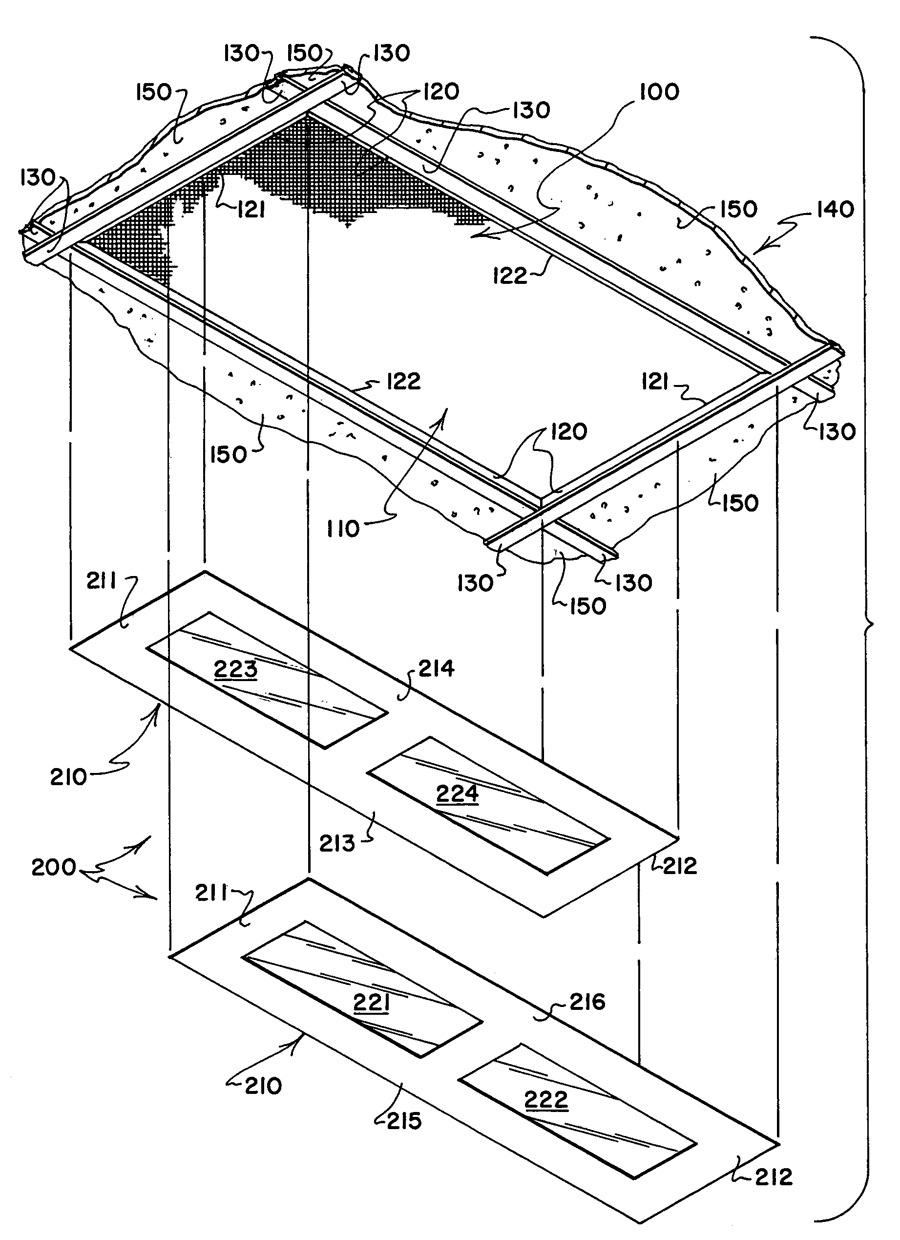
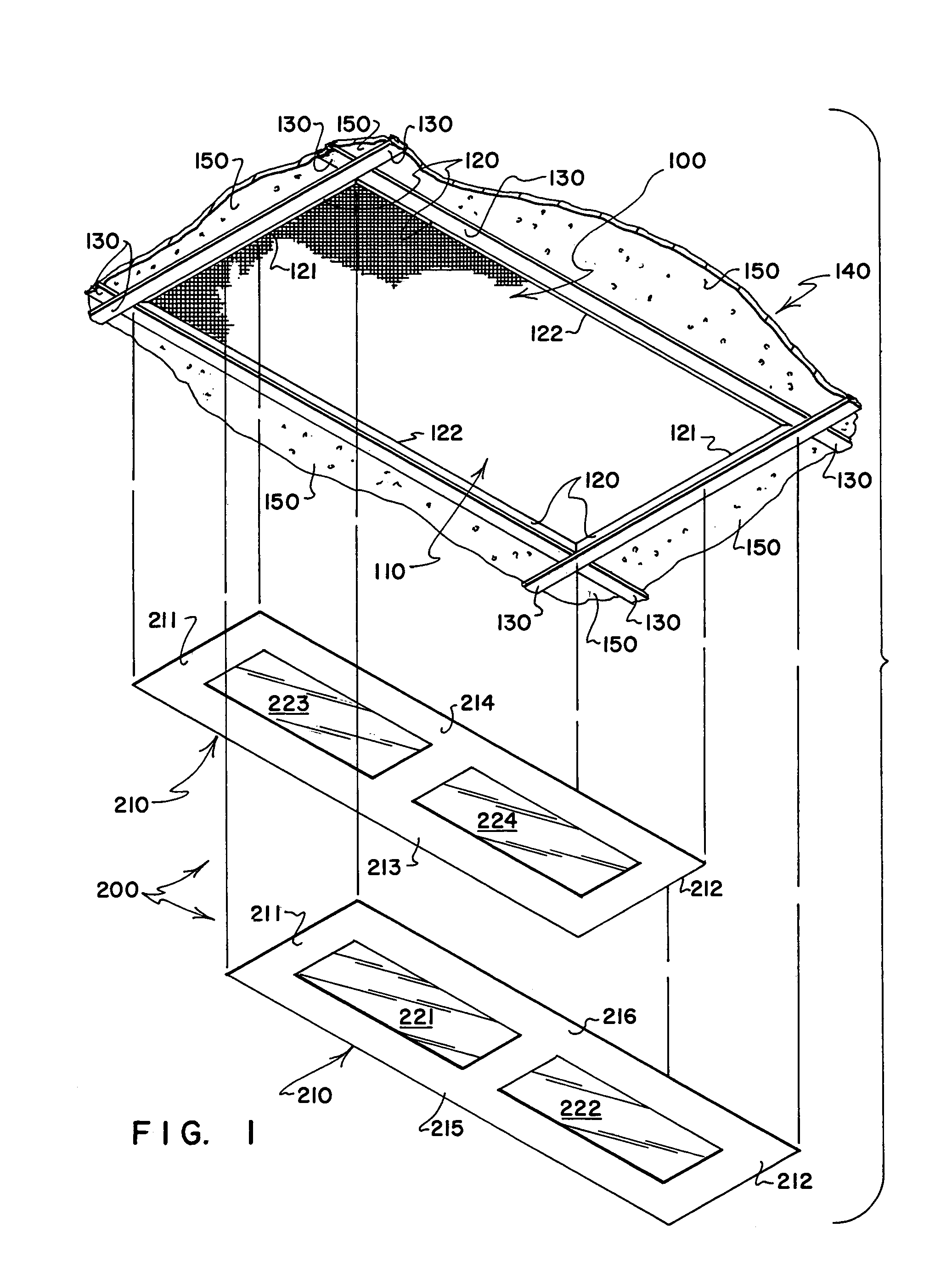
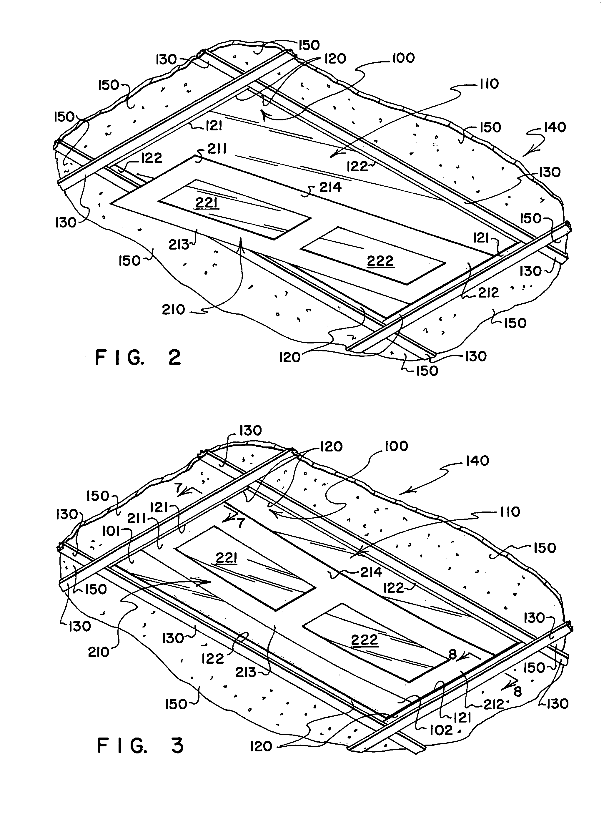
[0009]What the present invention provides are plural element paint shields 1) that can be installed quickly and easily to mask the lenses of light fixtures such as ceiling light fixtures in grid supported ceilings; 2) that also can be removed quickly and easily without causing damage to the paint shields and without leaving behind any tape or other residue; 3) that preferably are formed from inexpensive but durable stock that will permit their being reused a reasonable number of times; and 4) that, in their preferred form, permit fixture generated light to pass therethrough to illuminate the interiors of rooms where painting is underway so that auxiliary lighting systems need not be installed. Optionally the shields may be provided with visible guide formations along peripheral regions thereof to aid one in trimming the shields to accommodate fixtures of a variety of sizes, and may be provided with fold away or fold down portions to rigidify installed shields.
[0012]When working with fixtures that have at least two opposed parallel extending sides, it is preferred that all of the paint shield elements have a common dimension that substantially equals a selected one of the length and width dimensions of the light fixture lens that the paint shield elements are to protect—so that each of the paint shield elements, when installed, bridges the full width or the full length of the protectively covered lens so that opposite portions of each of the paint shield elements is supported by being inserted between a frame lip and an edge portion of the lens. And, in most preferred practice, at least one of the installed paint shield elements has a turn-away or fold-down portion that can be bent away from the plane of the protected lens so as to strengthen and rigidify at least the one paint shield element against sagging under the influence of the force of gravity.
[0014]In a most preferred form of the invention, each of the paint shield elements has a central region formed primarily from material that permits light from a light fixture on which the paint shield is installed to pass therethrough, and a surrounding peripheral region that is formed from opaque material. By forming at least central regions of at least selected ones of the paint shield elements from materials that are transparent or translucent, the shield permit fixture generated light to pass therethrough to illuminate the room wherein the fixtures are installed. Safety and efficiency are enhanced by utilizing fixture generated light to illuminate the room being painted, and by permitting light to pass through the transparent or translucent regions.
[0015]To stiffen paint shield elements and minimize sagging under the influence of the force of gravity, the paint shield elements may be provided with fold away or fold down portions that can be deflected out of a main plane occupied by major portions of the installed paint shield elements. To facilitate the folding of stiffener portions of the paint shield elements, marked fold lines or lines of weakness may be provided that show where folds are to be made in the material of the paint shield elements. Likewise, to facilitate trimming the paint shield elements to proper sizes to overlie the lenses of light fixtures of a variety of sizes, marked cutting lines or lines of weakness may be provided that extend along selected portions of the perimeters of the paint shield elements. If lines of weakness are to be provided to facilitate folding or trimming, the lines of weakness may take the form of linearly extending press-formed score lines, or an linear-extending array of press-formed perforations that cut through portions of the material of the paint shields where folds or cuts are to be made.

Problems solved by technology

When ceilings and / or ceiling grids and exposed light fixture frame surfaces are to be painted, what often is done is to tape sheets of newspaper or other disposable sheet stock to the lenses of light fixtures—a task that is labor intensive and hard on the backs and necks of the workers who have been hired to perform it—a task that typically requires many yards of tape and a great deal of patience to install the tape with a suitable degree of precision.
Where large rooms of commercial buildings have dozens of fluorescent fixtures in suspended tile ceilings that need their lenses masked to permit the perimetrically extending lens support components of the fixtures to be spray painted, it may require several people working for many hours, if not days, to complete the masking of the lenses; and, when the lenses are masked, relatively little fixture generated light may be permitted to escape into the room to illuminate the room during the painting process—a drawback that often needs to be addressed by providing auxiliary lighting to ensure that paint is properly applied.
When the paint has dried, an equally large amount of labor may be required to remove the masking materials and to remove tape residue.

Method used


Image

  • Paint shields for light fixtures
  • Paint shields for light fixtures
  • Paint shields for light fixtures

Examples


embodiment 300

[0045]What is intended to be illustrated by the three element paint shield embodiment 300 that is depicted in FIG. 9 is: 1) that paint shields that embody features of the present invention can be comprised of more than two paint shield elements; 2) that the paint shield elements of paint shields that embody features of the present invention need not be identical in size or in configuration; 3) that selected parts of overlapped regions of paint shields that embody features of the present invention may be designed to be folded away from a main plane occupied by major other portions of the paint shield, in this case by being folded or turned downwardly (or provided with some other form of stiffening formation that serves to stiffen the paint shield elements to prevent sag; and 4) that the stiffening formations of adjacent overlapped regions of adjacent paint shield elements may engage each other so as to assist in retaining the paint shield elements in their installed positions.

[0046]R...

embodiment 400

[0048]What is intended to be illustrated by the paint shield embodiment 400 depicted in FIG. 11 is that paint shield elements that embody features of the present invention do not need to be identically configured; nor do they necessarily each need to be provided with one or more central regions that are transparent or translucent. The depicted paint shield elements 410, 412 are neither identically configured, nor do they both carry transparent or translucent central regions—only the paint shield element 412 is provided with transparent central regions 414, while the paint shield element is formed from a single relatively stiff sheet of material that carries no transparent or translucent film.

[0049]As is depicted in FIGS. 11 and 12, overlapping portions of the paint shield elements 410, 412 have parts thereof cut away to permit their being turned to define depending elements 420, 422 that engage so as to stiffen the paint shield elements to prevent them from sagging while being insta...

embodiment 700

[0054]In the depicted paint shield embodiment 700, fold lines or lines of weakness 750 (typically formed by pressing the material of the paint shield elements 710 to compact it, or by press-slitting an array of openings through portions of the material of the paint shield elements 710) connect shield portions 760, 770 that can be turned or folded away from a plane occupied by major other portions of the installed paint shield elements, as depicted in FIG. 16 wherein one of each of the fold-down portions 760, 770 has been turned down.

[0055]In providing the paint shield elements of the present invention with turn-away or turn-down portions that can be pivoted or folded out of a main plane occupied by major other portions of an installed paint shield, the preferred approach taken by the present invention is to provide these turn-away or turn-down portions at one of two selected positions: either 1) adjacent where relatively thick, relatively heavy stock (i.e., material typically select...


PUM


Abstract

Paint shields formed from relatively stiff but pliable material are configured to cover the transparent or translucent lenses of light fixtures so that frames of the fixtures which extend perimetrically about the lenses can be painted by brush, by roller or by spray without getting paint on the lenses. Edge regions of the paint shields are configured to be inserted between the frames and the lenses, and central regions of the paint shields preferably are transparent or translucent to permit light from the fixtures to pass through the installed paint shields. Peripheral regions of the shields preferably are provided with visible guide formations or may be scored or perforated to facilitate trimming the shields to fit small and undersized fixtures. Central portions may be designed to fold away from other portions of the shields to stiffen the installed shields to minimize sagging.

Description

REFERENCE TO PROVISIONAL APPLICATION[0001]This application claims the benefit of U.S. Provisional Application Ser. No. 60 / 458,597 entitled PAINT SHIELDS FOR LIGHT FIXTURES filed Mar. 28, 2003 by Joseph A. Bechtold, Jr., the disclosure of which is incorporated herein by reference.BACKGROUND OF THE INVENTION[0002]1. Field of the Invention[0003]The present invention relates to paint shields formed from relatively stiff but pliable material configured to protectively cover the transparent or translucent lenses of light fixtures so that frame components of the fixtures which extend perimetrically about the lenses can be painted by brush, by roller or by spray without getting paint on the lenses. More particularly, the present invention relates to plural element paint shields having edge regions that can be temporarily inserted between edge regions of the lenses and their perimetrically extending frame components so the paint shields are supported by the same frame components that support...

Claims


Application Information

Patent Timeline
IPC IPC(8): B05C21/00
CPCB05B15/0481B05B15/0456B05B12/24B05B12/29
Inventor BECHTOLD, JR., JOSEPH A.
Owner BECHTOLD JR JOSEPH A
Learn More