
Gun for oriented perforation

Active Publication Date: 2020-05-21
TCO AS
View PDF0 Cites 11 Cited by
  • Summary
  • Abstract
  • Description
  • Claims
  • Application Information

AI Technical Summary

Benefits of technology

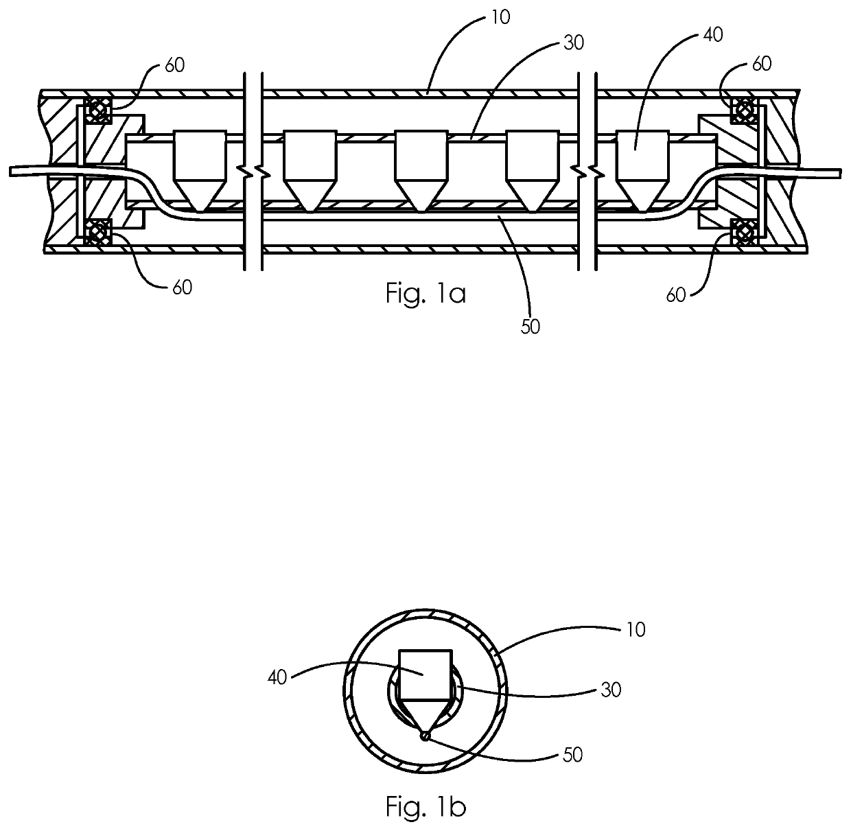
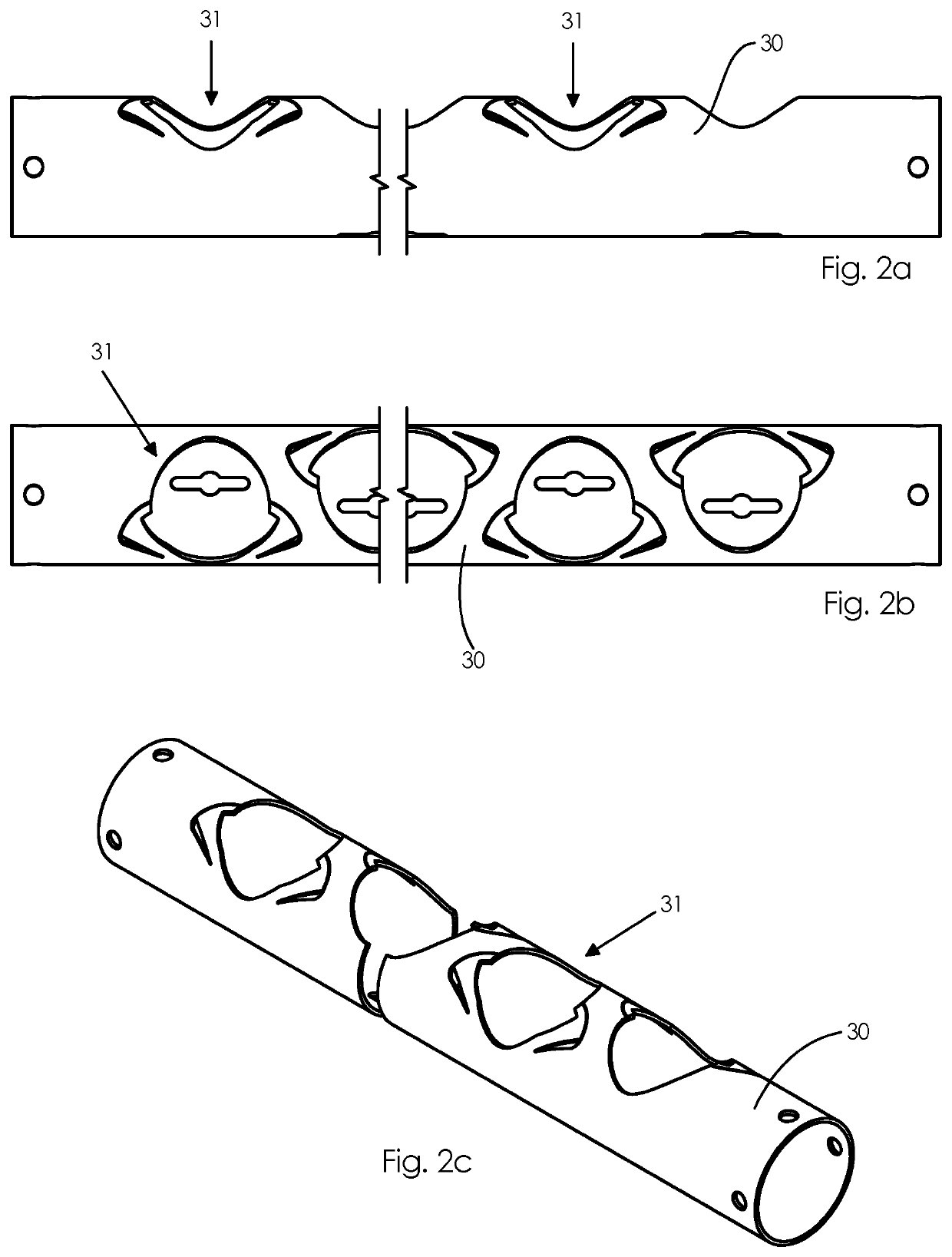
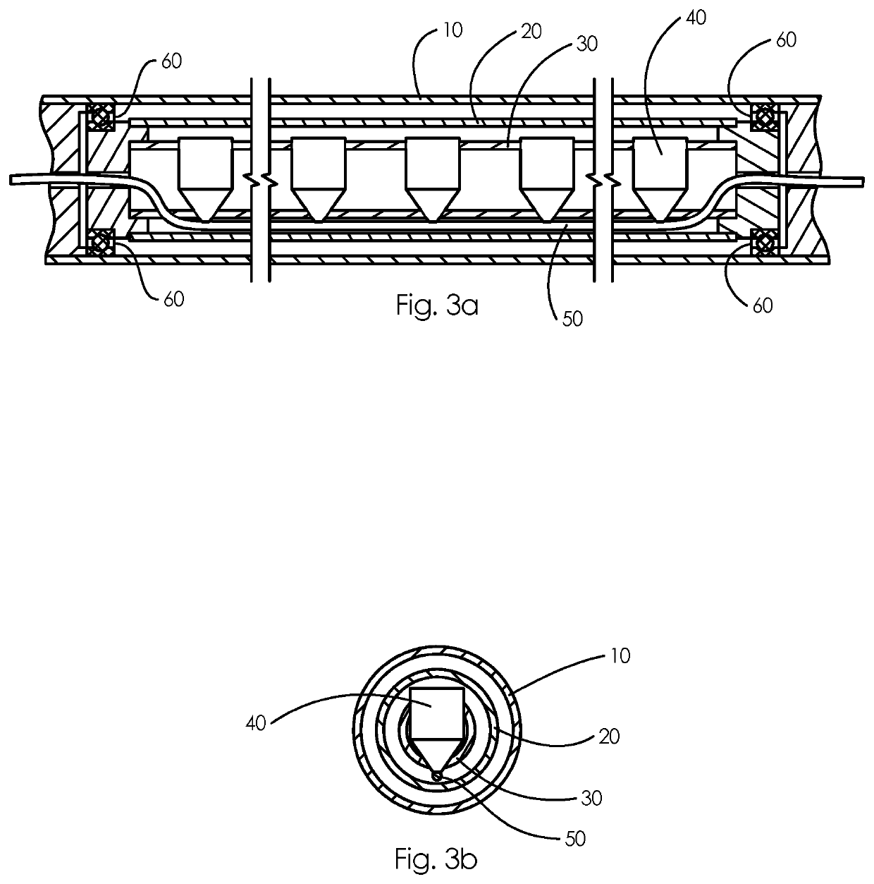
The present invention is about a new way to position charges inside a gun carrier to ensure they are properly oriented in relation to the borehole. This is achieved by rotating the charges inside the gun carrier. Additionally, the invention aims to make the rotating assembly containing the charges stiffer to minimize any bending or sagging between two supports due to its own weight and any objects it may be carrying, such as the weight of the charges.

Problems solved by technology

The main concern is damage to completion equipment.
Debris in borehole may cause damage to completion equipment such as plugs, packers and polished bore interfaces.
For example, setting packers in fluid with debris may cause leakage, and interfacing with a polished bore when debris is present will result in leakage and damage to the bore.
In addition, debris entering production fluid is not desirable.
Contact friction between the gun carrier and casing and debris in borehole may result in inaccurate and unreliable orientation.
Due to the weight of the charges and the loading tube itself, the loading tube can begin to sag.
As a result, this may cause the loading tube or the charges to rest on the inside of the gun carrier creating a friction great enough to prevent correct orientation of the charges.

Method used


Image

  • Gun for oriented perforation
  • Gun for oriented perforation
  • Gun for oriented perforation

Examples


Embodiment Construction

[0033]The following description of the exemplary embodiments refers to the accompanying drawings. The same reference numbers in different drawings identify the same or similar elements. The following detailed description does not limit the invention. Instead, the scope of the invention is defined by the appended claims. Reference throughout the specification to “one embodiment” or “an embodiment” means that a particular feature, structure or characteristic described in connection with an embodiment is included in at least one embodiment of the subject matter disclosed. Thus, the appearance of the phrases “in one embodiment” or “in an embodiment” in various places throughout the specification is not necessarily referring to the same embodiment. Further particular features, structures or characteristics may be combined in any suitable manner or in one or more embodiments.

[0034]The present invention relates to a gun for perforating a casing, liner or tubing of a well, one of the main p...


PUM


Abstract

A gun for perforating a casing, liner or tubing of a well comprising multiple perforating charges in a mounting fixture configured to rotate inside a gun carrier and orientate the charges to a predetermined direction relative to the casing, liner or tubing. The mounting fixture and the charges are carried by an orienting tube, and the orienting tube is rotatably supported inside the gun carrier, thereby creating a rotatable assembly for orienting the charges into a predetermined direction.

Description

FIELD OF THE INVENTION[0001]A gun for perforating a casing, liner or tubing of a well comprising multiple perforating charges in a mounting fixture configured to rotate inside a gun carrier and orientate the charges to a predetermined direction relative to the casing, liner or tubing.BACKGROUND OF THE INVENTION[0002]Well perforation is performed to provide flow communication between a cased wellbore and a reservoir. Perforation is performed by sending a tool string with one or more perforating guns downhole until the gun(s) reaches the desired location(s) for perforation. The perforating guns create perforations through the casing and cement and into the formation by use of explosive charges. When perforating a well, it is often beneficial to perforate in a specific direction or a specific range of directions relative to the borehole. There are several reasons for why oriented perforating is desirable, amongst others; avoid sand influx, prevent damage to downhole equipment, and enha...

Claims


Application Information

Patent Timeline
IPC IPC(8): E21B43/116E21B43/119
CPCE21B43/116E21B43/119E21B43/117
Inventor MELHUS, GEIR ARNEELBERT, JOSTEINGUEST, OLIVER
Owner TCO AS
Learn More