Pallet with flexible tensile reinforcement

a flexible tensile reinforcement and pallet technology, applied in the field of reinforced pallets, can solve the problems of pallets that can exhibit significant deformation, mainly compressive loading, and plastic pallets are more susceptible to creep, and achieve the effects of reducing sagging or deflection, reducing the risk of pallet damage, and being easy to mount and dismoun

Inactive Publication Date: 2000-04-25
CADILLAC PROD
View PDF29 Cites 39 Cited by
  • Summary
  • Abstract
  • Description
  • Claims
  • Application Information

AI Technical Summary

Benefits of technology

It is an object of the present invention to provide a pallet or the like which is reinforced to minimize sagging or deflection and which is resilient against permanent deformation.
It is another object to provide elongate flexible tensile members in a plastic pallet which provide reinforcement against sagging while not being susceptible to permanent deformation laterally about their longitudinal axes.
It is yet another object to provide a pallet with an adjustable tensioner and a flexible tensile member in which the tension can be adjusted to control the amount of deflection of the pallet in response to a load of a predetermined magnitude.
A further object is to provide a pallet with a flexible tensile member which is easily mounted and dismounted relative to the body of the pallet.

Problems solved by technology

One disadvantage that plastic pallets have relative to wood pallets is that the plastic pallets are more susceptible to creep.
Pallets are often stacked one atop another resulting in primarily compressive loading.
If the temperature in the surroundings in which the pallets are stored becomes sufficiently high, and the pallets are kept on the racks for an extended period of time with heavy loads thereon, these pallets can exhibit significant deformation due to creep.
A first problem is that the steel bars can become permanently deformed thus permanently deforming the overall pallets.
In these cases, the steel bars and surrounding pallets may have permanent, and often undesirable, deformations formed therein.
Another problem is that using thick steel bars with substantial cross-sectional area to provide stiffness against lateral deflection or bending also significantly increases the overall weight of the pallet.
An additional problem associated with insert molding rigid steel bars within pallets is that the steel bars have a propensity to work their way through the plastic.
The protruding bars may snag objects or make otherwise flush surfaces bulge.

Method used


Image

  • Pallet with flexible tensile reinforcement
  • Pallet with flexible tensile reinforcement
  • Pallet with flexible tensile reinforcement

Examples


Embodiment Construction

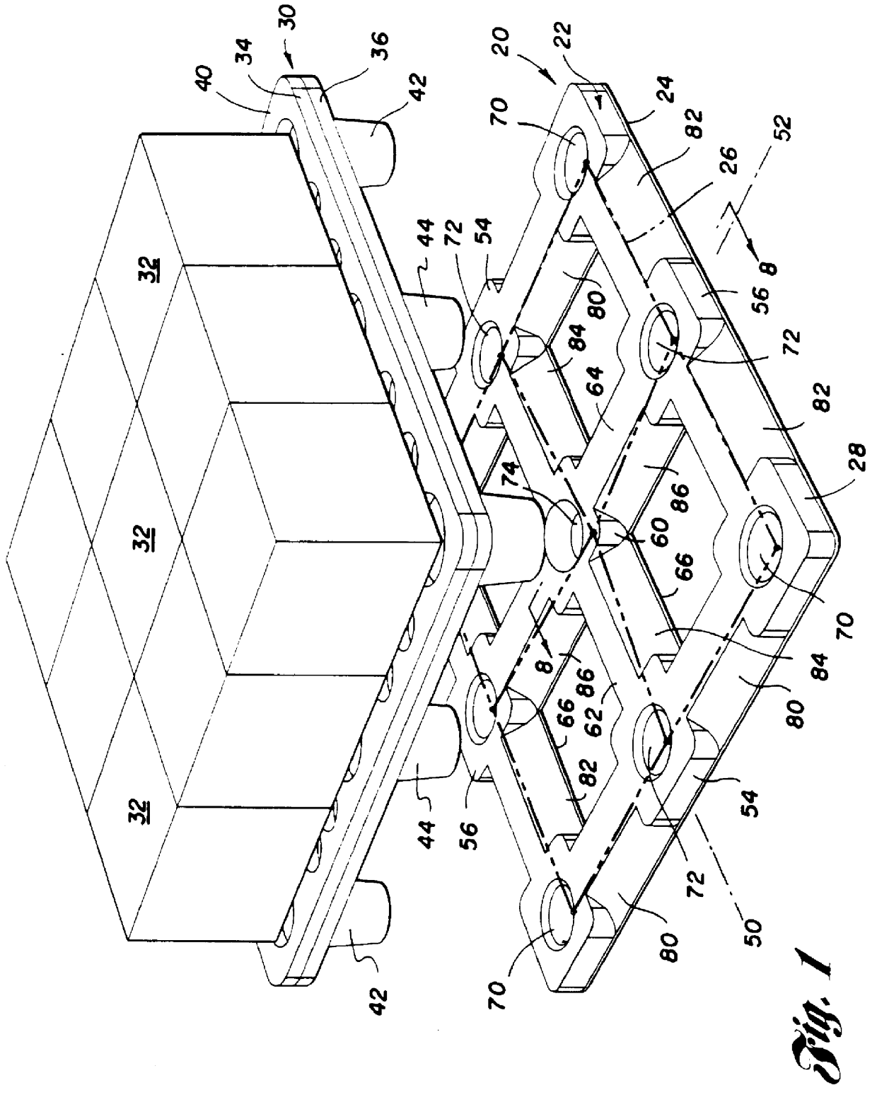
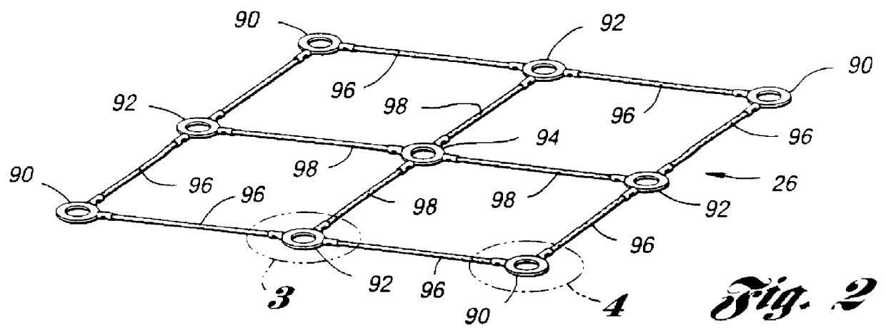
A load distributor pallet 20, made in accordance with a first embodiment of the present invention, is shown in FIG. 1. Distributor pallet 20 comprises an upper deck 22, a lower deck 24 and a flexible tensile member or mesh 26 disposed therebetween. Preferably, both upper and lower decks 22 and 24 are made of a thermoplastic resin material such as a high density polyethylene. Heated sheets of the polyethylene are vacuum formed and fused together using a twin-sheet thermoforming process, such as described in U.S. Pat. No. 3,925,140, to form a combined plastic body 28. Further details regarding the molding of distributor pallet 20 will be described below. Decks 22 and 24 of body 28 are joined at numerous discrete engineered fusion or knit points.

Located above distributor pallet 20 is a load pallet 30 upon which boxes 32 or other objects may be stacked. Preferably, load pallet 30 has an upper deck 34 and a lower deck 36 which are joined in a twin-sheet thermoforming process. Upper deck ...


PUM


Abstract

A reinforced pallet (20) and method for making the same are disclosed. The pallet (20) includes a body (28) having a pair of laterally spaced apart edge portions (56) with a central span (60) extending therebetween. A flexible tensile member (26) extends between the edge portions (56) and generally beneath the central span (60). The tensile member (26) may be in the form of a mesh affixed between upper and lower decks (22,24) of the pallet (20). When the edge portions (56) of the pallet (20) are simply supported and a load is place atop the pallet (20), the central span (60) of the pallet (20) will vertically deflect in response to the load. The central span (60) will bear upon the tensile member (26) with the tensile member providing support against deflection. A method for retrofitting a pallet (200) includes adding a tensile member (210) to the pallet (200) to reduce the amount of deflection of the pallet (200) when simply supported in response to a load placed atop the pallet (200).

Description

INCORPORATION BY REFERENCEThe disclosure of U.S. Ser. No. 08 / 220,965, entitled Load Distributor For Pallets, filed Mar. 31, 1994, is hereby incorporated by reference in its entirety.This invention relates to reinforced plastic pallets.Pallets made of thermoplastic materials are rapidly replacing old wood-type pallets. The plastic pallets have been proven to be lightweight, resilient, inexpensive to manufacture, and can easily be configured in different shapes due to their molded construction.One disadvantage that plastic pallets have relative to wood pallets is that the plastic pallets are more susceptible to creep. Even at relatively low temperatures, such as 80.degree. F. to 120.degree. F., the permanent deformation of the plastic pallets under load can be significant.Pallets are often stacked one atop another resulting in primarily compressive loading. In other instances, pallets may be stored in racks. The racks have opposing ledges upon which laterally spaced edge portions of t...

Claims


Application Information

Patent Timeline
Patent Type & Authority Patents(United States)
IPC IPC(8): B65D19/00
CPCB65D19/0026B65D19/0036Y10S248/903B65D2519/00034B65D2519/00069B65D2519/00104B65D2519/00129B65D2519/00273B65D2519/00293B65D2519/00318B65D2519/00333B65D2519/00373B65D2519/00432B65D2519/00437B65D2519/00442B65D2519/00562Y10T156/1002
Inventor JORDAN, RICHARD ALANYESTREPSKY, JOHN EDWARDGOSNELL, RAYMOND H.BROOKS, RICHARD GEORGE
Owner CADILLAC PROD
Why Eureka
Try Eureka