Imaging apparatus and image recording method

a technology of image recording and imaging apparatus, which is applied in the direction of instruments, television systems, and television system scanning details, etc., can solve the problems of large signal processing time, inability to reproduce an accurate reproduction area of recorded image data, and generally longer imaging intervals, so as to reduce image in a relatively short time

Active Publication Date: 2006-04-18
FUJIFILM CORP
View PDF4 Cites 10 Cited by
  • Summary
  • Abstract
  • Description
  • Claims
  • Application Information

AI Technical Summary

Benefits of technology

[0010]The present invention has been made in consideration of the above situation, and its object is to provide an imaging apparatus and an image recording method capable of creating a reduced image suitable for simplified display in a short time and generating a reduced image capable of appropriately representing the content of a reproduction area of recorded image data when recording RAW data.
[0012]According to the first aspect, images of an object are taken by the first imaging device and the second imaging device at the same time, or imaging is performed multiple times at very short time intervals. Thereby, the optical images of the object are converted to electric signals, and high-sensitivity image information and low-sensitivity image information are acquired. When each of the high-sensitivity image information acquired from the first imaging device and the low-sensitivity image information acquired from the second imaging device is recorded as RAW data (data which has not been processed by an image processing engine), a reduced image is generated only from one of the high-sensitivity image information acquired from the first imaging device and the low-sensitivity image information acquired from the second imaging device, and the reduced image is recorded on a recording medium together with the RAW data (first and second RAW data). Thus, it is possible to create a reduced image in a relatively short time.
[0013]It is also possible to configure the first imaging device to be also used as the second imaging device. In this case, imaging is performed multiple times under different exposure conditions at short intervals of time to acquire high-sensitivity image information and low-sensitivity image information.
[0015]The S / N ratio of the high-sensitivity image information acquired according to the present invention is more desirable than that of the low-sensitivity image information. Therefore, by creating a reduced image from the high-sensitivity image information, a vivid (high-contrast) reduced image can be obtained. On the other hand, the dynamic range against brightness of the low-sensitivity image information is wider than that of the high-sensitivity image information. Therefore, by creating a reduced image from the low-sensitivity image information, it is possible to obtain the reduced image in which the luminance range of the entire image is represented more appropriately though the contrast is somewhat weak.
[0019]By using the configuration in which power source to circuit sections unnecessary in the RAW recording mode can be separately shut off, it is possible to realize power saving in recording RAW data.
[0027]According to the present invention, a reduced image is generated only from one of high-sensitivity image information or low-sensitivity image information when RAW data is recorded, and the reduced image is recorded on a recording medium together with the RAW data (first and second RAW data). Thereby, it is possible to create the reduced image in a relatively short time.

Problems solved by technology

However, if more than two images taken under different exposure conditions are synthesized, and then a thumbnail is created from the synthesized image as in the dynamic-range-magnification imaging mode in Japanese Patent Application Laid-open No. 2002-44515 or as described in Japanese Patent Application Laid-open No. 2002-305684, a lot of time is required for signal processing.
Especially, in a mode for recording RAW data in which image information acquired from an imaging element has not been processed, an imaging interval is generally longer because of a large amount of recording data.
However, this has a disadvantage that a part of the long-exposure image data may be saturated depending on scenes and thereby it may be impossible to reproduce an accurate reproduction area of recorded image data (the long-exposure image data and the short-exposure image data).

Method used


Image

  • Imaging apparatus and image recording method
  • Imaging apparatus and image recording method
  • Imaging apparatus and image recording method

Examples


Embodiment Construction

[0038]Embodiments of an imaging apparatus and an image recording method according to the present invention will be now described below with reference to accompanying drawings.

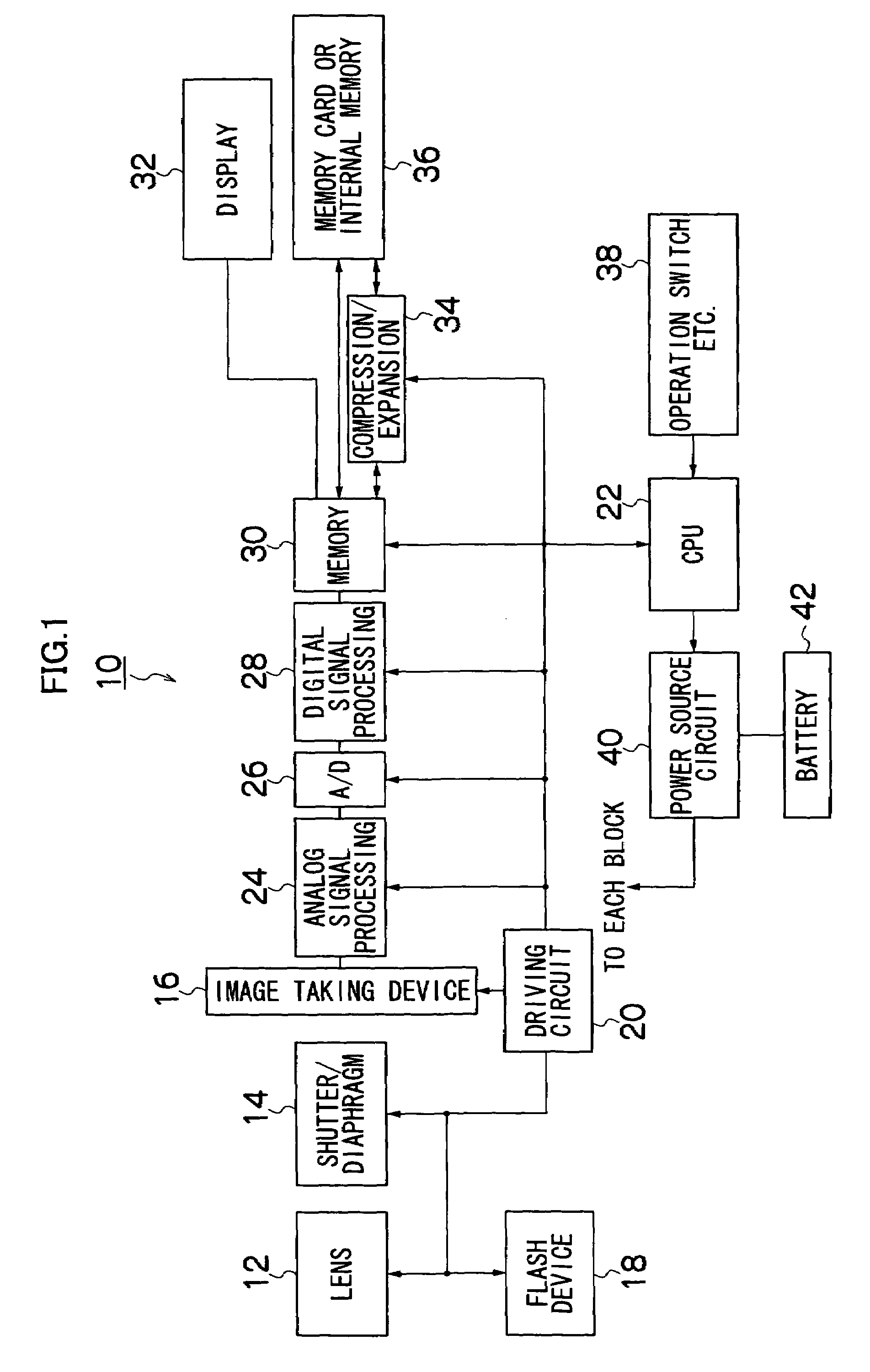
[0039]FIG. 1 is a block diagram showing the configuration of an imaging apparatus according to an embodiment of the present invention. The imaging apparatus 10 is a digital camera which converts an optical image of an object to digital image data and records it. A light passing through an imaging lens 12 and a shutter / diaphragm mechanism 14 is focused on the light receiving surface of an image taking device 16. The mechanical shutter prevents smears and the like from being caused by a light entering the image taking device 16 when a signal is read from the image taking device 16. The image taking device 16 may be configured with the mechanical shutter omitted. As the diaphragm mechanism, a single diaphragm or multiple switchable diaphragms can be applicable.

[0040]A flash device 18 which emits an auxiliary light...


PUM


Abstract

According to the present invention, a reduced image is generated only from one of high-sensitivity image information or low-sensitivity image information when RAW data is recorded, and the reduced image is recorded on a recording medium together with the RAW data (first and second RAW data). Thereby, it is possible to create the reduced image in a relatively short time. In this case, if a reduced image is generated from the high-sensitivity image information, a high-contrast image with a desirable S / N ratio can be acquired. If a reduced image is generated from the low-sensitivity image information, an image appropriately representing the content of a reproduction area of the RAW data can be acquired.

Description

BACKGROUND OF THE INVENTION[0001]1. Field of the Invention[0002]The present invention relates to an imaging apparatus and an image recording method, and in particular to a technique suitable for a digital still camera capable of recording a wide dynamic range image and used for a RAW data recording function in which unprocessed data (RAW data) outputted from an imaging element such as a CCD is immediately recorded.[0003]2. Related Art[0004]Japanese Patent Application Laid-open No. 2002-44515 discloses a digital camera having a dynamic-range-magnification imaging mode and a two-screen imaging mode in addition to a usual imaging mode. When imaging is performed in the dynamic-range-magnification imaging mode or the two-screen imaging mode by the digital camera shown in the document, long exposure and short exposure are performed, and long-exposure image data and short-exposure image data of the same object are generated.[0005]In the dynamic-range-magnification imaging mode, a synthesiz...

Claims


Application Information

Patent Timeline
Patent Type & Authority Patents(United States)
IPC IPC(8): H01L27/00H04N3/14H04N1/32H04N5/225H04N5/232H04N5/765H04N5/91H04N101/00
CPCH04N1/2158H04N1/32128H04N2201/325H04N2201/0084H04N2101/00
Inventor MISAWA, TAKESHI
Owner FUJIFILM CORP
Why Eureka
Try Eureka