Ionization gauge

a technology of ionizing gauges and gauges, which is applied in the direction of vacuum gauges, fluid pressure measurement, instruments, etc., can solve the problems of reducing the emission characteristics of electron sources, reducing the number of electrons generated, and reducing the operational life, so as to reduce the number of electrons and reduce the operational life

Active Publication Date: 2006-04-18
MKS INSTR INC
View PDF24 Cites 15 Cited by
  • Summary
  • Abstract
  • Description
  • Claims
  • Application Information

AI Technical Summary

Benefits of technology

[0004]The operational lifetime of a typical ionization gauge is approximately ten years when the gauge is operated in benign environments. However, these same gauges and electron sources (filaments) fail in minutes or hours when operated at too high a pressure or in gas types that degrade the emission characteristics of the electron source. Examples of such filament interactions leading to decreased operational lifetime range from degradation of the electron emission properties of the oxide coating on the filament to exposure to water vapor. Degradation of the oxide coating dramatically reduces the number of electrons generated by the filament, and exposure to water vapor results in the complete burnout of a tungsten filament.

Problems solved by technology

However, these same gauges and electron sources (filaments) fail in minutes or hours when operated at too high a pressure or in gas types that degrade the emission characteristics of the electron source.
Examples of such filament interactions leading to decreased operational lifetime range from degradation of the electron emission properties of the oxide coating on the filament to exposure to water vapor.
Degradation of the oxide coating dramatically reduces the number of electrons generated by the filament, and exposure to water vapor results in the complete burnout of a tungsten filament.
However, RGAs measure additional signal peaks that are entirely spurious to the gas species being detected.

Method used


Image

  • Ionization gauge
  • Ionization gauge
  • Ionization gauge

Examples


Embodiment Construction

[0015]A description of preferred embodiments of the invention follows.

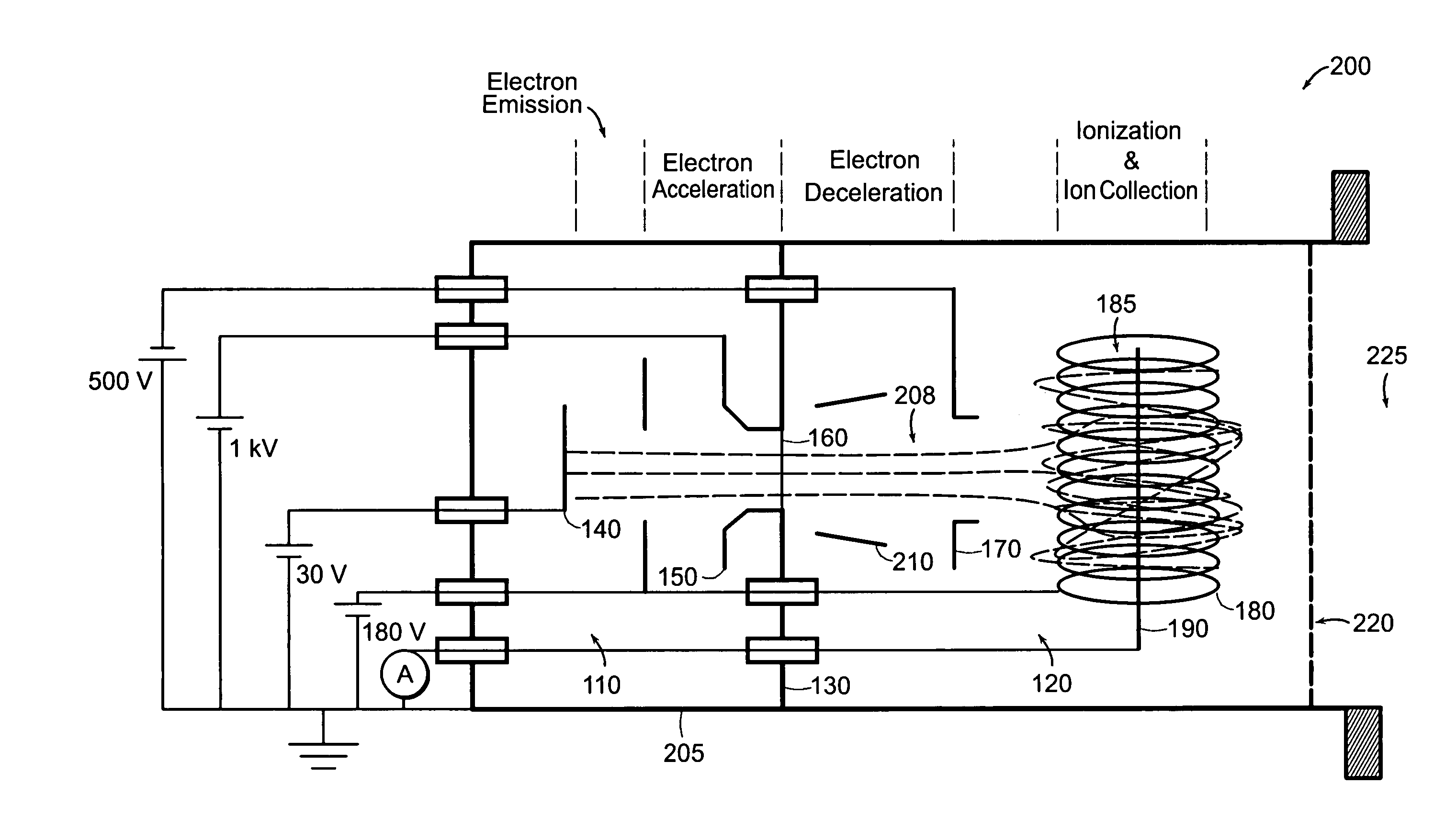
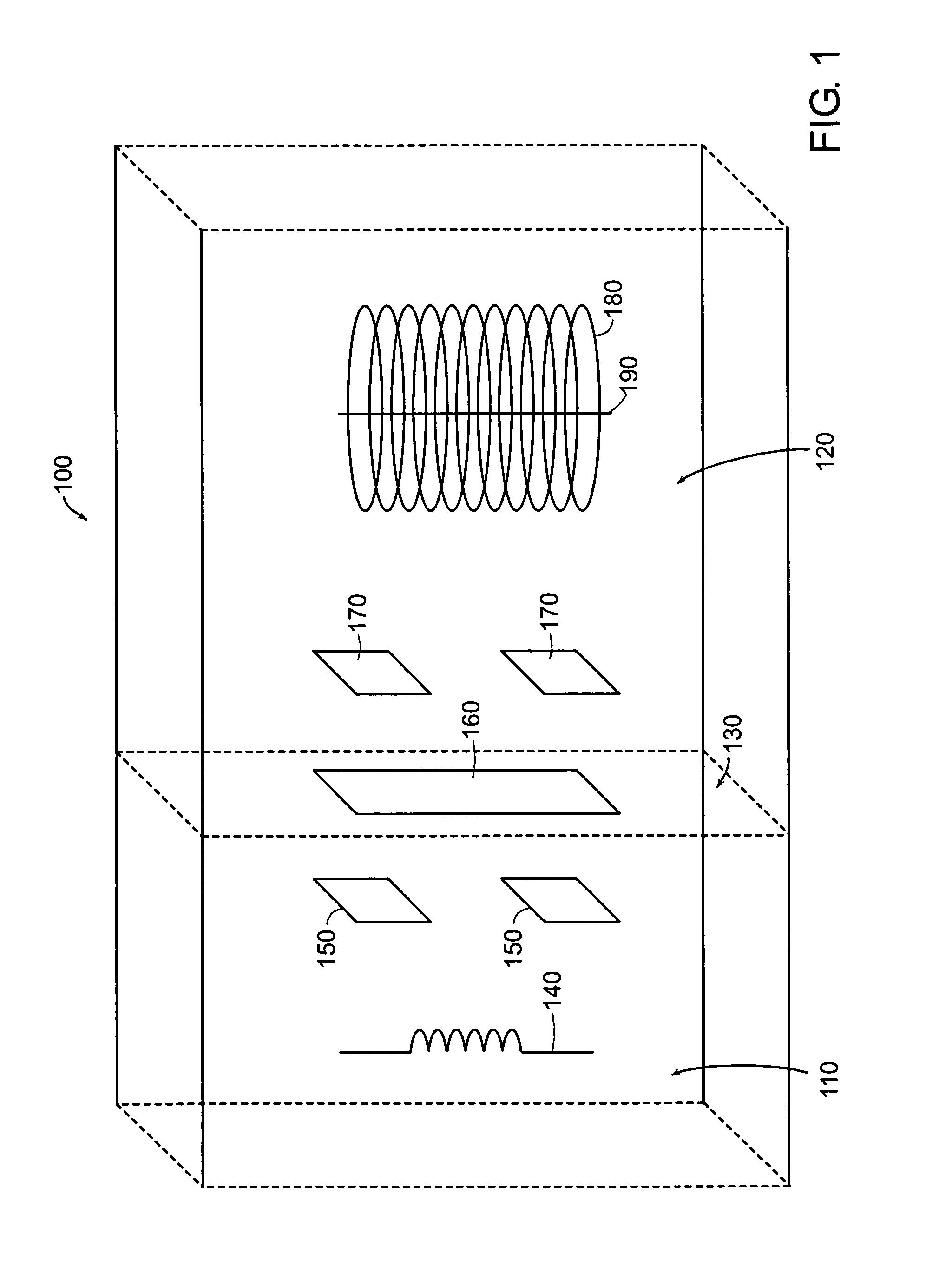
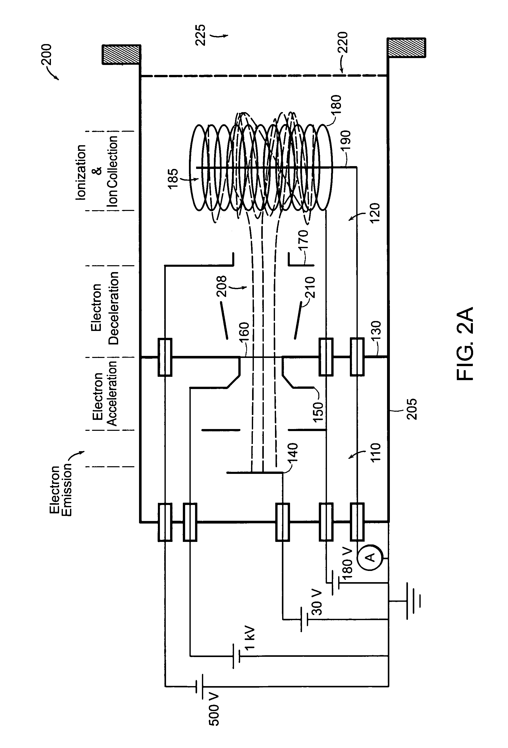
[0016]Generally, as shown in FIG. 1, one ionization gauge 100 of the present invention has an isolation chamber 110 and a measurement chamber 120. The isolation chamber contains at least one electron source 140 and at least one acceleration electrode 150. The measurement chamber 120 contains at least one deceleration electrode 170, an anode 180, and at least one collector electrode 190. The two chambers 110, 120 are separated by an isolation material 130 which prevents molecules and atoms of gas within the measurement chamber 120 from entering the isolation chamber 110 and degrading the electron source(s) 140. The isolation material 130 has an electron window 160 which allows electrons to be transmitted from the isolation chamber 110 into the measurement chamber 120. Although the ionization gauge 100 is shown with an anode 180 and collector electrode 190, these components are not needed in all embodiments of the i...


PUM

PropertyMeasurementUnit
electric potentialaaaaaaaaaa
energyaaaaaaaaaa

Abstract

An ionization gauge for isolating an electron source from gas molecules includes the electron source for generating electrons, a collector electrode for collecting ions formed by the impact between the electrons and gas molecules, and an electron window which isolates the electron source from the gas molecules. The ionization gauge can have an anode which defines an anode volume and retains the electrons in a region of the anode. The ionization gauge can have a plurality of electron sources and / or collector electrodes. The collector electrode(s) can be located within the anode volume or outside the anode volume. The ionization gauge can have a mass filter for separating the ions based on mass-to-charge ratio. The ionization gauge can be a Bayard-Alpert type that measures pressure or a residual gas analyzer that determines a gas type.

Description

RELATED APPLICATION[0001]This application is a continuation-in-part of U.S. application Ser. No. 10 / 782,368, filed Feb. 19, 2004, now abandoned; the entire teachings of which are herein incorporated by reference.BACKGROUND OF THE INVENTION[0002]Ionization gauges, more specifically Bayard-Alpert (BA) ionization gauges, are the most common non-magnetic means of measuring very low pressures and have been widely used worldwide since being disclosed in U.S. Pat. No. 2,605,431 in 1952.[0003]A typical ionization gauge includes an electron source, an anode, and an ion collector electrode. For the BA gauge, the electron source is located radially outside of an ionization space (anode volume) defined by the anode. The ion collector electrode is disposed within the anode volume. Electrons travel from the electron source toward and through the anode, and are eventually collected by the anode. However, in their travel, the electrons impact molecules and atoms of gas, constituting the atmosphere ...

Claims


Application Information

Patent Timeline
Patent Type & Authority Patents(United States)
IPC IPC(8): G01L21/30G01N27/62G01L21/32H01J41/00H01J41/04
CPCH01J41/04G01L21/32
Inventor ARNOLD, PAUL C.RUTT, PAUL M.
Owner MKS INSTR INC
Why Eureka
Try Eureka