
Method for driving plasma display panel and plasma display panel

a plasma display panel and display panel technology, applied in the direction of electrical discharge tubes, instruments, electrical equipment, etc., can solve the problems of enlarging the screen size of lcd displays, unsuitable crts for large-screen 40 inch plus applications, and limitations in viewing angles, so as to prevent erroneous discharge, high-quality image display, and crosstalk elimination

Inactive Publication Date: 2006-04-18
PANASONIC CORP
View PDF19 Cites 8 Cited by
  • Summary
  • Abstract
  • Description
  • Claims
  • Application Information

AI Technical Summary

Benefits of technology

[0025]With a view to overcoming the problems discussed above, an object of the invention is to provide a plasma display panel (PDP) drive method and a plasma display device that prevent erroneous discharge from occurring in the address period. Crosstalk can thus be eliminated and high quality image display achieved.

Problems solved by technology

CRTs, currently the most widely used type of display, exhibit excellent resolution and image quality characteristics, although the substantial increases in unit depth and weight that accompany increases in screen size make CRTs unsuitable for large-screen 40 inch plus applications.
There are, however, technical difficulties associated with enlarging the screen size of LCD displays, and also limitations concerning the viewing angle.
However, when priming particles crossover into lines adjacent to the ith line, causing the discharge initiating voltage Vfs to decrease in the cells in these lines, there exists the possibility that an erroneous discharge will be initiated between the first and second electrodes in these cells in period T4.

Method used


Image

  • Method for driving plasma display panel and plasma display panel
  • Method for driving plasma display panel and plasma display panel
  • Method for driving plasma display panel and plasma display panel

Examples


Embodiment Construction

[0067]A preferred embodiment of the present invention will now be described in detail with reference to the drawings, the invention of course not being limited to this embodiment.

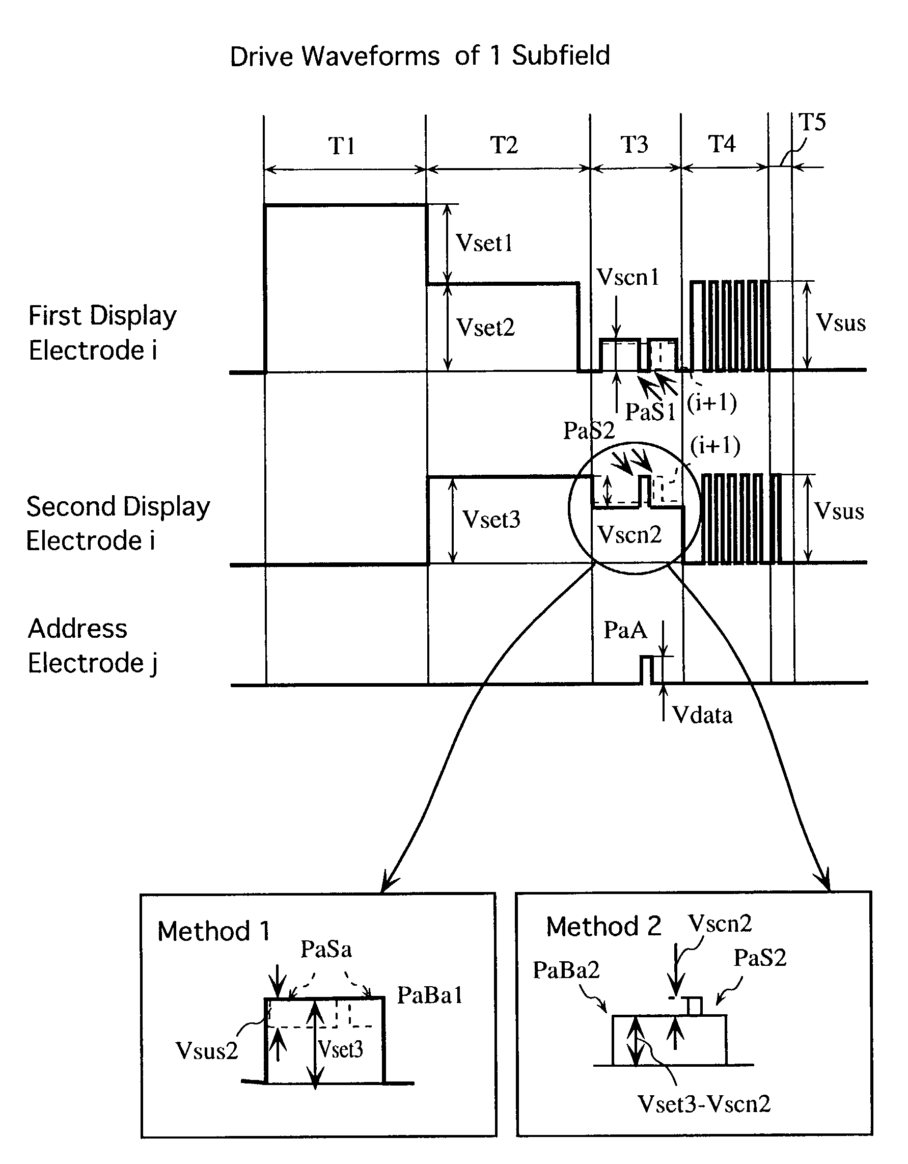
[0068]FIG. 5 shows drive waveforms of a method for driving the PDP according to the present embodiment.

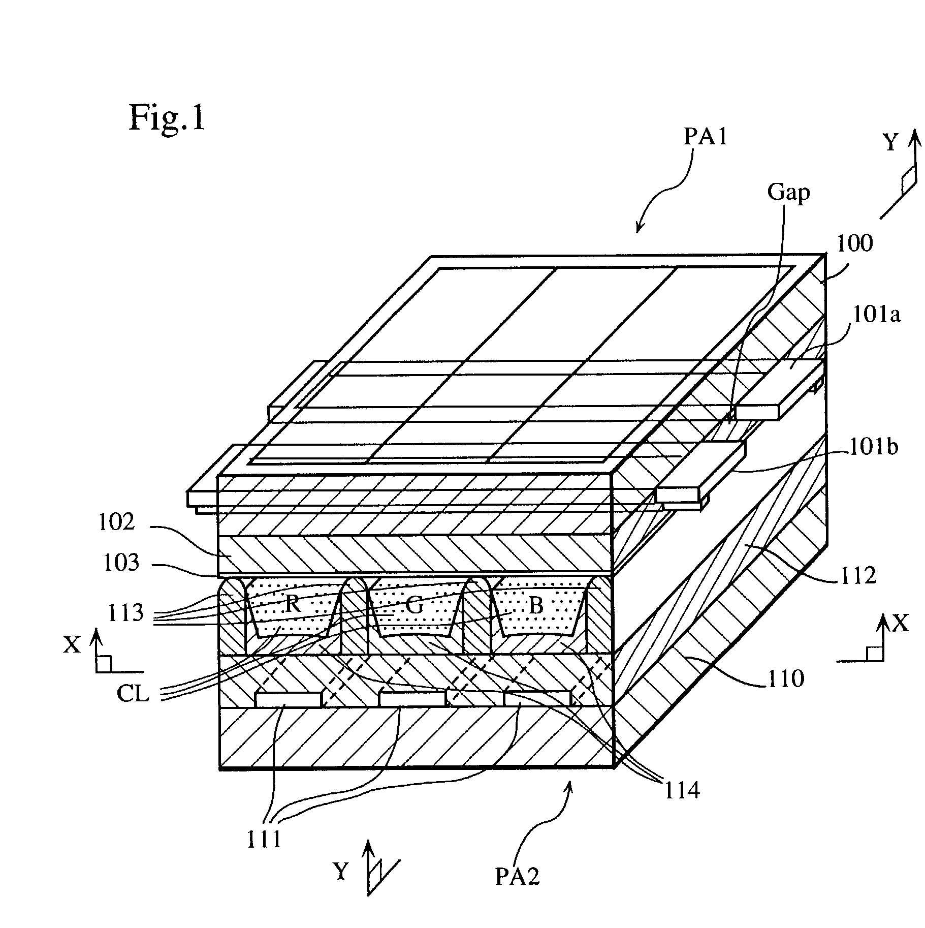
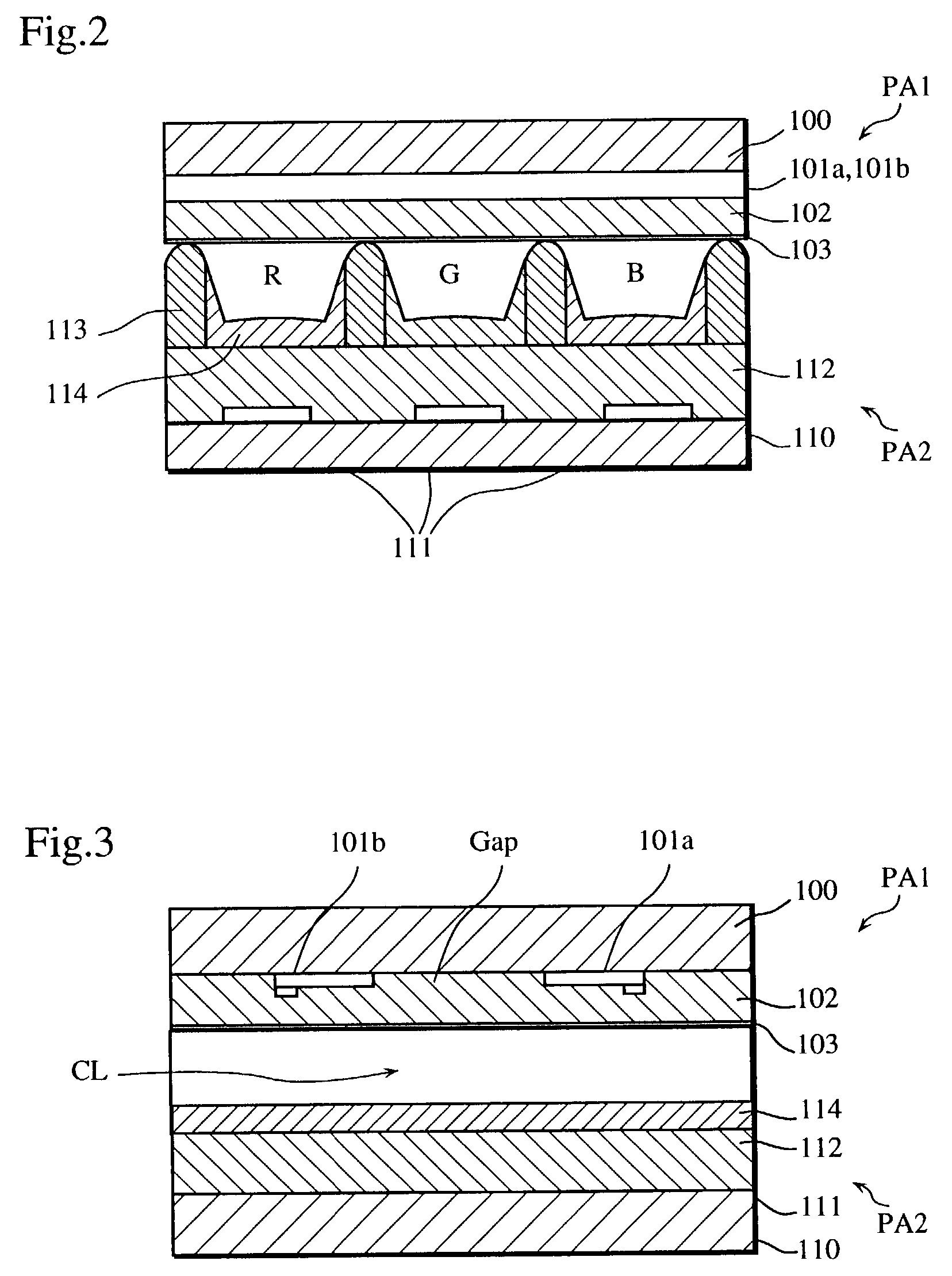
[0069]The structure of the PDP according to the present embodiment as shown in FIGS. 1, 2 and 3 is the same as the prior art PDP, and for this reason will not be described in detail here.

[0070]As with the prior art PDP, the PDP of the present embodiment uses a field timesharing display method. According to this method, one display field is divided into a plurality of subfields, and each subfield is composed of a plurality of operation periods: a first initializing period T1, a second initializing period T2, an address period T3, a sustain period T4, and an erase period T5. An illumination weight of each subfield is determined by the number of sustain pulses applied in sustain period T4, and the gradations ...


PUM


Abstract

A plasma display panel (PDP) drive method eliminates crosstalk and allows for high quality image display by preventing erroneous discharge from occurring in an address period. The method includes an address step of writing data by applying an address pulse to a third electrode and a scan pulse Pas1 sequentially to first electrodes, and a sustain step of sustaining an illumination by applying sustain pulses between first and second electrodes after completion of the address step. Furthermore, in the address step, a scan pulse Pas2 of opposite polarity to scan pulse Pas1 is applied to a second electrode in a pair with a first electrode in a selected line (i.e. a line in which scan pulse Pas1 is being applied).

Description

TECHNICAL FIELD[0001]The invention relates to a plasma display panel (PDP) drive method and a plasma display device used for image display in computers, televisions, and the like.BACKGROUND ART[0002]Developments in cathode-ray tube (CRT), liquid crystal display (LCD), and plasma display panel (PDP) technology has been spurred in recent years by increasing demand for large screen televisions having high definition capabilities, an example of which is hi-vision.[0003]CRTs, currently the most widely used type of display, exhibit excellent resolution and image quality characteristics, although the substantial increases in unit depth and weight that accompany increases in screen size make CRTs unsuitable for large-screen 40 inch plus applications. The advantage of LCDs, on the other hand, lies in their economical power usage and the consequent low drive voltages. There are, however, technical difficulties associated with enlarging the screen size of LCD displays, and also limitations con...

Claims


Application Information

Patent Timeline
Patent Type & Authority Patents(United States)
IPC IPC(8): G09G3/28G09G3/296G09G3/293H01J11/00
CPCG09G3/293G09G2320/0209G09G3/296
Inventor HIGASHINO, HIDETAKANAGAO, NOBUAKI
Owner PANASONIC CORP
Learn More