Supercharge Your Innovation With Domain-Expert AI Agents!

Operating knob for an optical system

a technology of optical systems and knobs, applied in the field of operating knobs for optical systems, can solve the problems of axial the slipping of the actuating fingers, and the inability to safely grip the coarse focus driv

Active Publication Date: 2006-04-18
LEICA MICROSYSTEMS CMS GMBH +1
View PDF11 Cites 3 Cited by
  • Summary
  • Abstract
  • Description
  • Claims
  • Application Information

AI Technical Summary

Benefits of technology

[0006]It is the object of the invention is to create a coaxial operating knob for an optical system which allows an ergonomic operation and thereby ensures that inadvertent faulty operation is impossible.
[0008]It is a further object of the invention is to provide a microscope with an operating knob which allows an ergonomic operation of the microscope.
[0010]The invention has the advantage that the operating knob has a first and a second rotating element, whereby the second rotating element at the side directly opposing the first rotating element forms a circumferential step which has approximately the size of the diameter of the first rotating element.

Problems solved by technology

State of the art focus drives often have the disadvantage that conditionally to too small circumferential surfaces in the area of the coarse focus drive no safe gripping of the coarse focus drive is possible.
Additionally, too extending fine focus drives interfere with the fingers while actuating the coarse focus drive.
A too conical form of both rotating elements leads to an axial slipping of the actuating fingers.
Also a too strong surface profile affects the tactile sensitiveness of the fingers tips disadvantageously in the long term, and the adhesive friction between the user's hand and the rotating element is unnecessarily reduced, which reduces the adjusting accuracy and additionally brings about the danger that the user unintentionally actuates the coarse focus while actuating the fine focus.
The reason is that both rotating elements are arranged in a way to each other that the smaller focus drive penetrates the larger coarse focus drive as a cylinder and thus the abutting face of the coarse focus drive can be touched while the fine focus is being actuated, and thus the coarse focus drive is actuated unintentionally.
This occurs especially to microscopes with a non-mechanical transmission (in the case of a mechanical transmission the coarse focus moves so clumsily that this danger hardly exists).
Concerning these microscopes, the focus drives move almost friction-free, which enables unintentional actuation, and which may lead to the damage to or even the demolition of the sample and / or of the optical system in the worst case.
Concerning state of the art focus drives, this effect of the unintentional actuation of the coarse focus drive is also increased by that the rotating element for the fine focus drive by a haptic way indicates insufficiently how close already the fingers of the user are to the abutting face of the coarse focus drive.

Method used


Image

  • Operating knob for an optical system
  • Operating knob for an optical system
  • Operating knob for an optical system

Examples


first embodiment

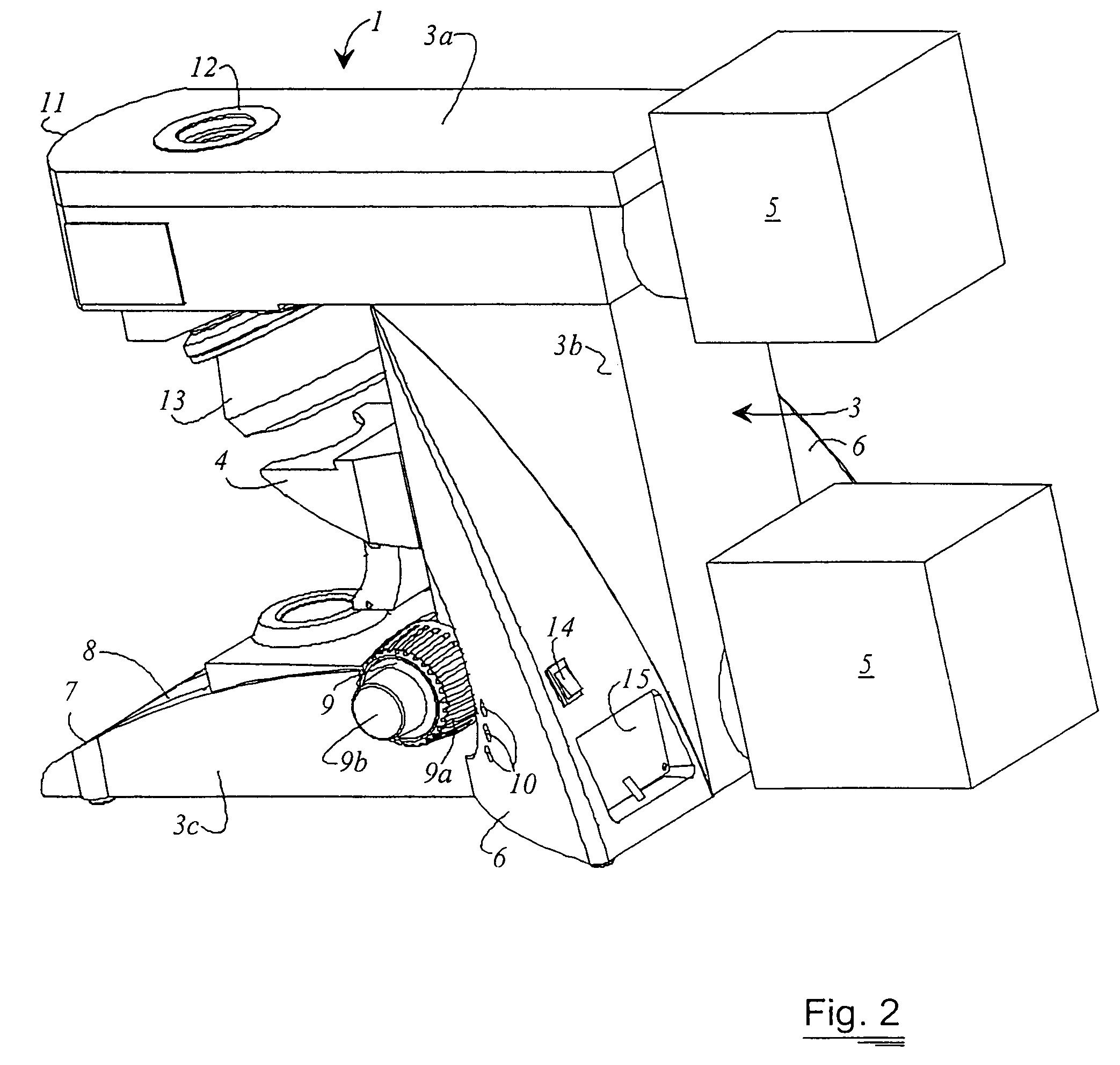
[0024]FIG. 3 shows a side view of an operating knob 20 according to the invention. Normally, the operating knob 20 is used for the coarse and the fine adjustment of an optical system 100. For example, the optical system 100 can be a standard microscope 1. The operating knob 20 according to the invention is the most relevant element for positioning. In FIG. 3 the optical system 100 is partly shown to demonstrate the arrangement of the operating knob 20 at the optical system 100. The operating knob 20 comprises of a first and a second rotating element 21 and 22 both of which are arranged coaxially around a common axis 23. The first and the second rotating element 21 and 22 are rotatable independently around the axis 23. The first rotating element 21 abuts directly at the optical system 1. The second rotating element 22 is arranged downstream of the first rotating element 21. The first and the second rotating element 21 and 22 have at least partly conical form, and the first rotating e...

second embodiment

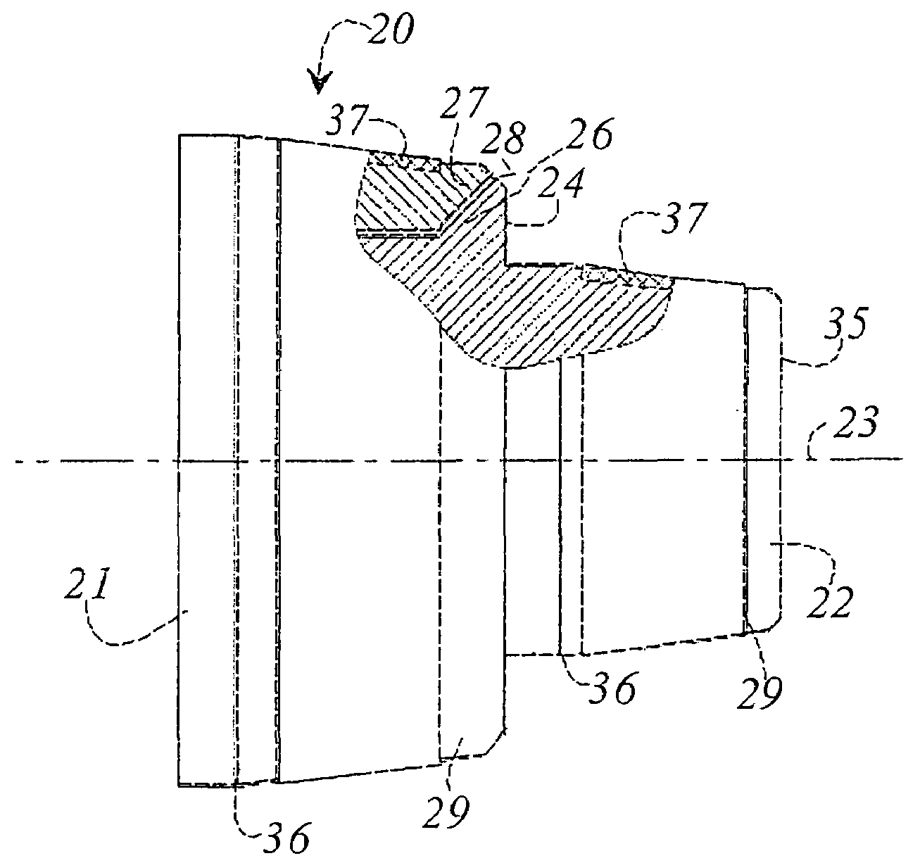
[0025]FIG. 4 shows a side view of the operating knob 20, whereby parts of the first and the second rotating element 21 and 22 are shown as a sectional drawing to demonstrate the cooperation of the first and the second rotating element 21 and 22. As already described in FIG. 3. the second rotating element 22 has a step 24 which approximately has the diameter of the first rotating element 21. The first rotating element 21 has a cone shaped depression 27, formed in the direction to the axis 23. Also step 24 of the second rotating element 22 has a cone shaped flank 26, so that both elements can be matched into one another and interact in a way that between the first and the second rotating element 21 and 22 a separating groove 28 is formed. By the separating groove 28, a free rotation of the first rotating element 21 with respect to the second rotating element 22 is possible, also the position of the separating groove 28 ensures that while actuating the second rotating element 22 no uni...


PUM


Abstract

An operating knob (20) for an optical system (100) is disclosed. The operating knob (20) has a first and a second coaxially arranged rotating element (21, 22). The first and the second rotating element (21, 22) have at least partly conical form. The first rotating element (21) has at the side directly opposing the second rotating element (22) a larger diameter than the second rotating element (22) and a step is formed at the side of the second rotating element (22) directly opposing the first rotating element (21), wherein the step possesses a diameter which is approximately the diameter of the first rotating element.

Description

CROSS REFERENCE TO RELATED APPLICATIONS[0001]The invention claims priority of the German patent application 103 14 752.7 which is incorporated by reference herein.FIELD OF THE INVENTION[0002]The present invention concerns an operating knob for an optical system. The invention concerns as well a microscope with an operating knob.BACKGROUND OF THE INVENTION[0003]Normally, focus knobs are designed as coaxially arranged rotating elements which are mounted aside the microscope, whereby the larger focus knob actuates the coarse focus and the smaller focus knob actuates the fine focus.[0004]State of the art focus drives often have the disadvantage that conditionally to too small circumferential surfaces in the area of the coarse focus drive no safe gripping of the coarse focus drive is possible. Additionally, too extending fine focus drives interfere with the fingers while actuating the coarse focus drive. A too conical form of both rotating elements leads to an axial slipping of the actua...

Claims


Application Information

Patent Timeline
IPC IPC(8): G02B21/26G02B21/24G05G1/10
CPCG05G1/10G02B21/242
Inventor PETER, KAJTABOEHMEL, PHILLIPKNOLL, CHRISTIANKEMPF, DIETMAR
Owner LEICA MICROSYSTEMS CMS GMBH
Features
  • R&D
  • Intellectual Property
  • Life Sciences
  • Materials
  • Tech Scout
  • Unparalleled Data Quality
  • Higher Quality Content
  • 60% Fewer Hallucinations
Learn More