Disk drive having guide-vanes

a technology of guide tubes and disk drives, applied in the field of disk drives, can solve the problems of increasing tmr, vibration of those components, and airflow impinging on the disk drive components, and achieve the effect of reducing the turbulent flow of air

Inactive Publication Date: 2006-04-18
WESTERN DIGITAL TECH INC
View PDF32 Cites 71 Cited by
  • Summary
  • Abstract
  • Description
  • Claims
  • Application Information

AI Technical Summary

Benefits of technology

[0007]It is an object of this invention to decrease turbulent flow of air in the space between a surface

Problems solved by technology

This airflow impinges upon the disk drive components and causes vibrations in those components.
These vibrations cause relative motion between the tracks on the disks and

Method used


Image

  • Disk drive having guide-vanes
  • Disk drive having guide-vanes
  • Disk drive having guide-vanes

Examples


Embodiment Construction

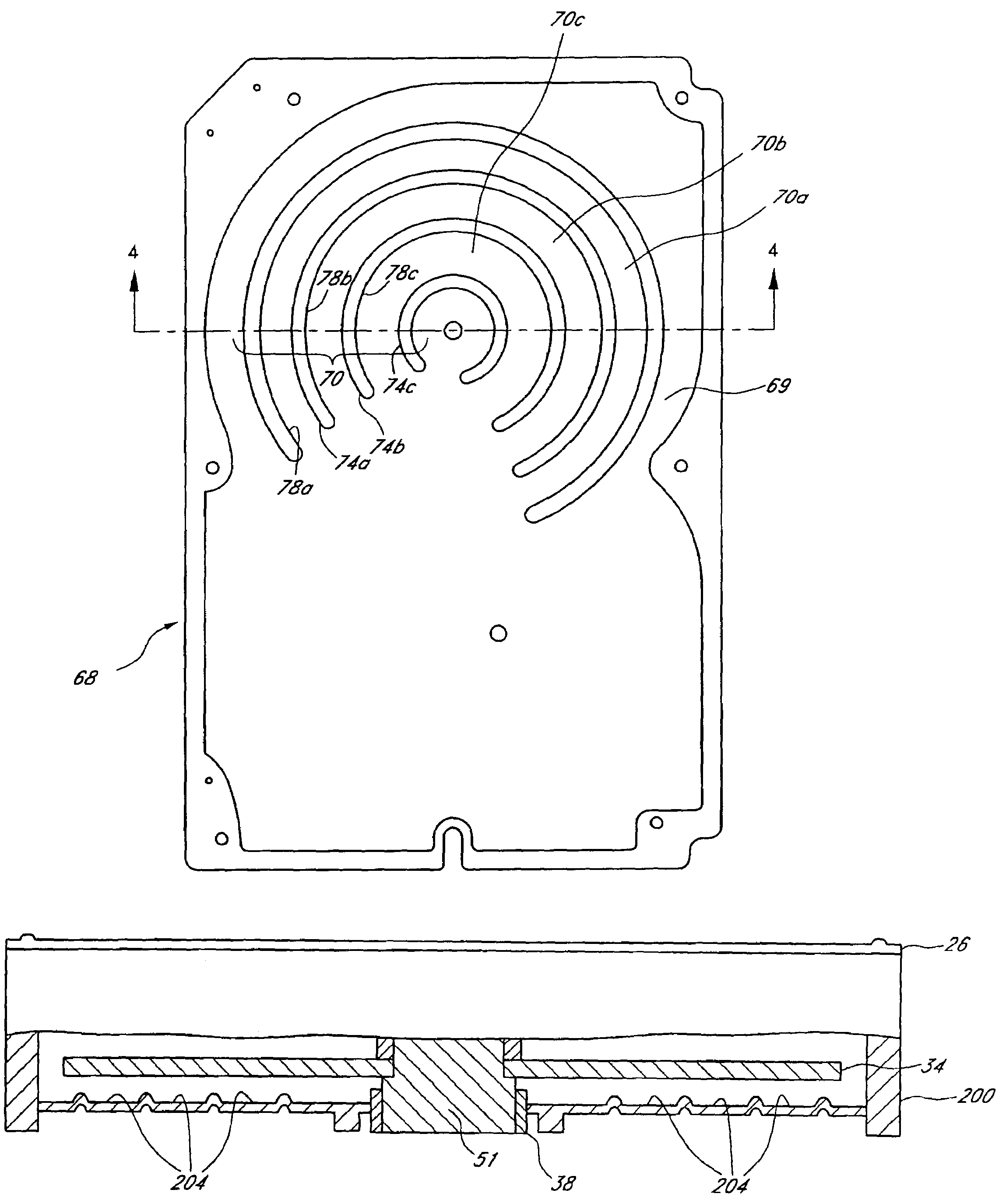
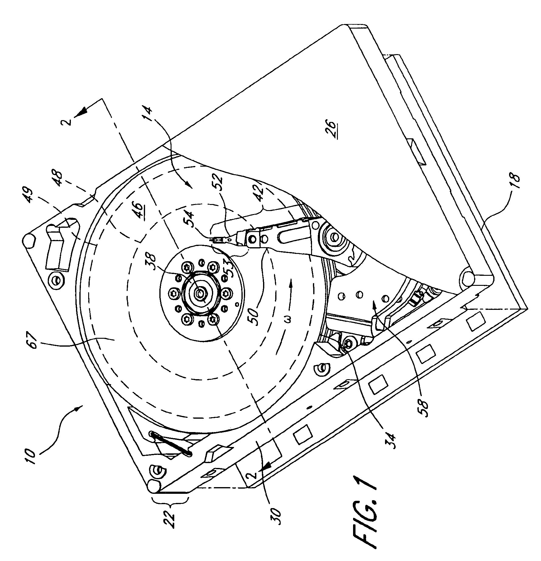
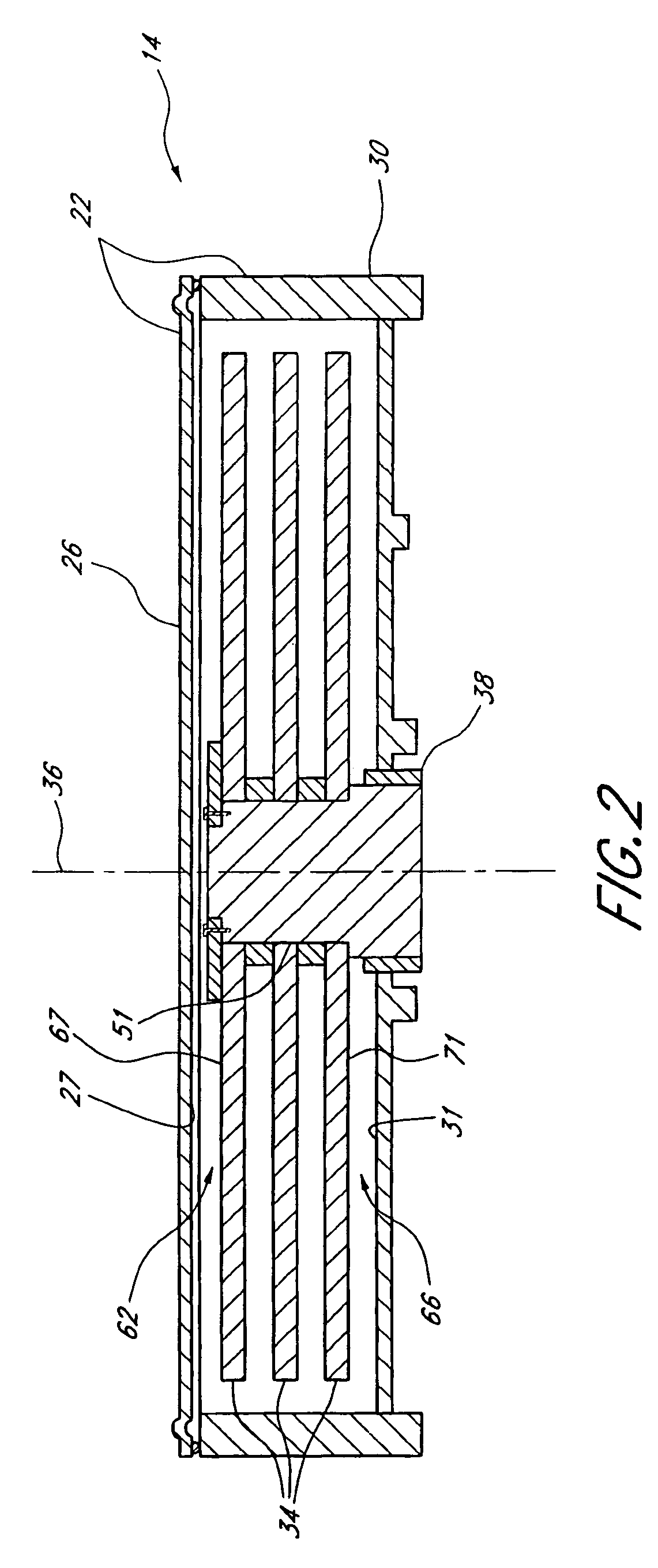
[0026]FIG. 1 is a perspective view of a disk drive 10. The disk drive 10 includes a head-disk assembly (HDA) 14 and a printed circuit board 18. The HDA 14 comprises an enclosure 22 that includes a cover 26 and a base 30. The cover 26 has an inner surface 27 that faces the internal components of the disk drive 10 when the disk drive 10 is assembled. The base 30 has an inner surface 31 that faces the internal components of the disk drive 10 when the disk drive 10 is assembled. The printed circuit board 18 is connectable to the base 30, but is shown removed therefrom in FIG. 1 for illustration. The HDA 14 also includes at least one disk 34, a spindle motor assembly 38, and a head-stack assembly (HSA) 42. In the illustrated embodiment, the disk drive 10 includes three disks 34. The disks 34 are rotatable within the enclosure 22 about an axis 36. Each disk 34 is mounted on the spindle motor assembly 38. One skilled in the art will recognize that the disk drive claimed herein includes mor...


PUM


Abstract

A disk drive includes an enclosure, a rotatable disk and an actuator arm, and also includes a plurality of arcuate channels. Airflow is created within the enclosure when the disk rotates. The plurality of arcuate channels facing the disk to decrease the turbulence of the airflow with respect to the actuator arm. The arcuate channels are formed on at least one portion of the enclosure.

Description

BACKGROUND OF THE INVENTION[0001]1. Field of the Invention[0002]This application relates to a disk drive and more particularly relates to the construction of the components that enclose the disks within the disk drive.[0003]2. Description of the Related Art[0004]One type of data storage device used in a computer to permanently store data is a disk drive. A disk drive includes at least one disk with a magnetic medium that is mounted on and rotated by a spindle motor. The disk drive also includes a data transfer head that writes data onto the magnetic medium and that reads data from the medium in concentric, generally circular tracks. In most applications, the data transfer head is extended out over the magnetic medium by an actuator assembly that moves the head in an arcuate path with respect to the medium. The tracks on the disk are divided into sectors, which are presented to the data transfer head by the rotation of the disk. An enclosure surrounds these components of the disk dri...

Claims


Application Information

Patent Timeline
IPC IPC(8): G11B33/14G11B5/54
CPCG11B5/6005G11B33/14G11B33/08G11B5/40
Inventor BUTT, ARAFAT M.CODILIAN, RAFFIPONG, KIN-CHEOK
Owner WESTERN DIGITAL TECH INC
Why Eureka
Try Eureka