Method for partial data reallocation in a storage system

a storage system and partial data technology, applied in the field of storage systems, can solve the problems of increasing storage capacity, difficult to increase the number of physical disk drives, and large amounts of data must be moved among the physical disk drives, so as to achieve the effect of reducing i/o performance, sacrificing disk capacity, and improving i/o efficiency

Inactive Publication Date: 2006-04-18
HITACHI LTD
View PDF8 Cites 8 Cited by
  • Summary
  • Abstract
  • Description
  • Claims
  • Application Information

AI Technical Summary

Benefits of technology

[0011]Numerous advantages or benefits are achieved by way of the present invention over conventional techniques. In a specific embodiment, the present invention provides improved I / O efficiency without sacrificing disk capacity. Also, in some embodiments, data in a storage system can be reconfigured among a greater number of physical disks without decreasing I / O performance during the reconfiguration. One or more of these advantages may be present depending upon the embodiment.

Problems solved by technology

But this technology has a restriction that once physical disk drives are configured as a logical disk drive with some number of physical disk drives, it is difficult to increase the number of the physical disk drives to, for example, increase storage capacity of the logical disk or to increase parallelism of I / O processing.
Thus, when adding a physical disk to the logical disk configuration, large amounts of data must be moved among the physical disk drives.
Such data movement takes a long time and consumes processing power of the storage system, decreasing the I / O performance of the storage system.
Additionally, current storage systems do not utilize disk capacity efficiently.
But making multiple copies of all the data doesn't use disk capacity efficiently.
The copying of rarely accessed data increases I / O performance only slightly, while consuming disk capacity.

Method used


Image

  • Method for partial data reallocation in a storage system
  • Method for partial data reallocation in a storage system
  • Method for partial data reallocation in a storage system

Examples


Embodiment Construction

Overview

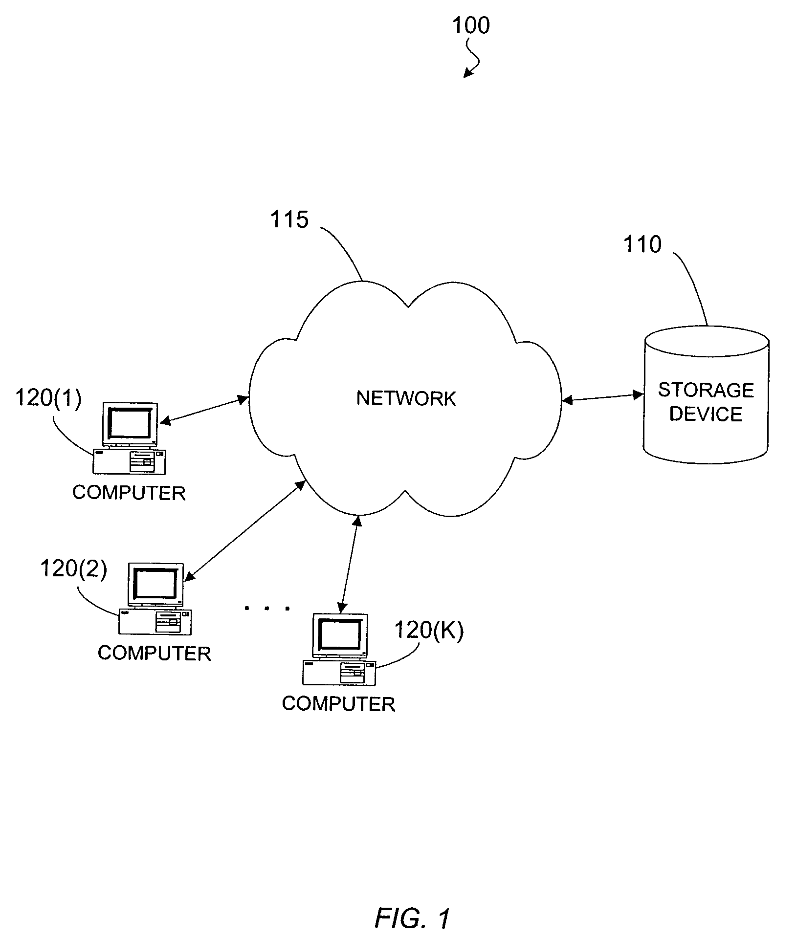
[0034]FIG. 1 is a simplified block diagram illustrating an example of a system in which the present invention may be embodied. The system 100 includes a storage device 110, coupled with a network 115. Additionally, one or more computers 120 are also coupled with the network 110. Computers 120 can access data stored on the storage system 110 via the network 115. In another embodiment, one or more computers 120 may be coupled with the storage device 110 directly instead of via a network.

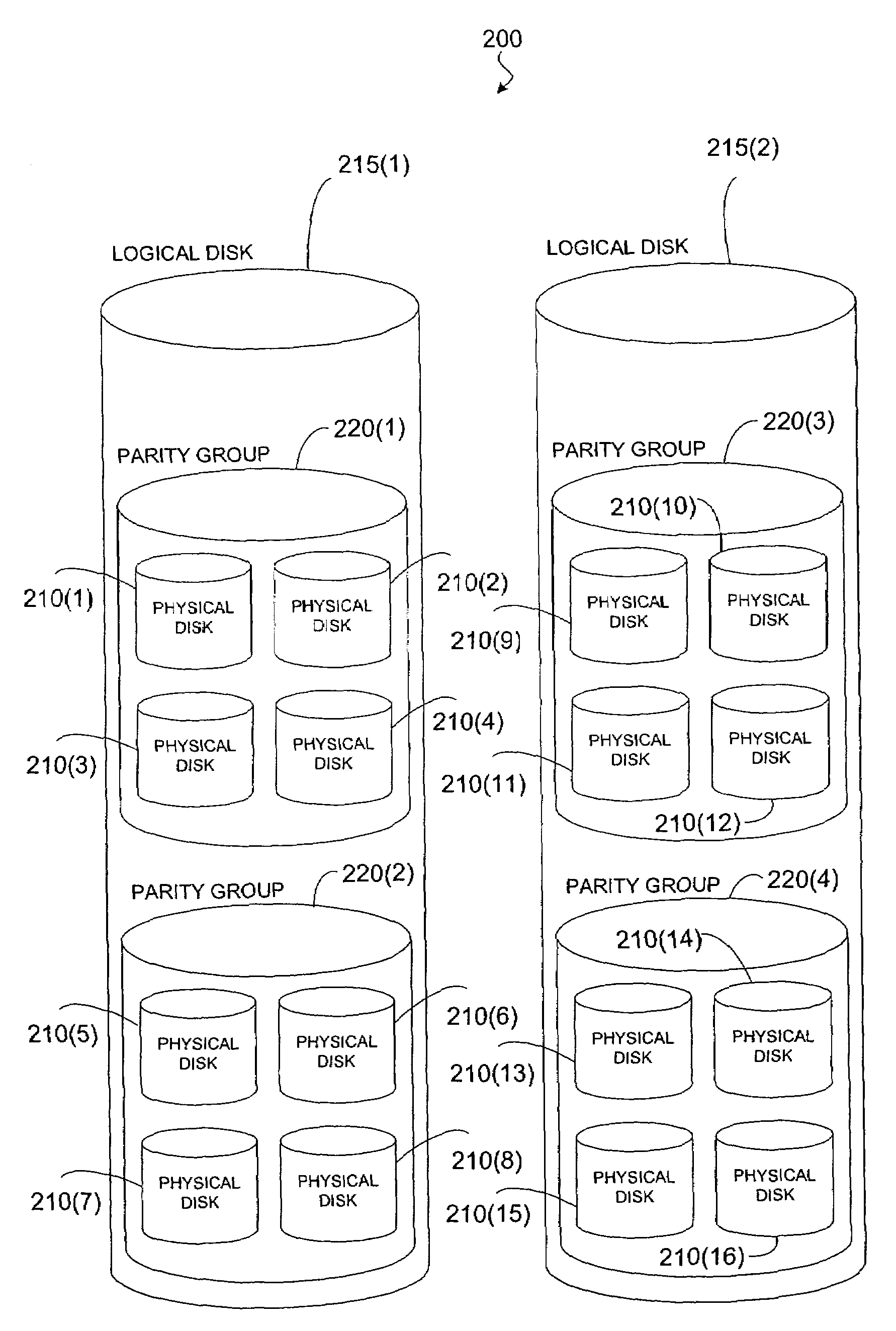
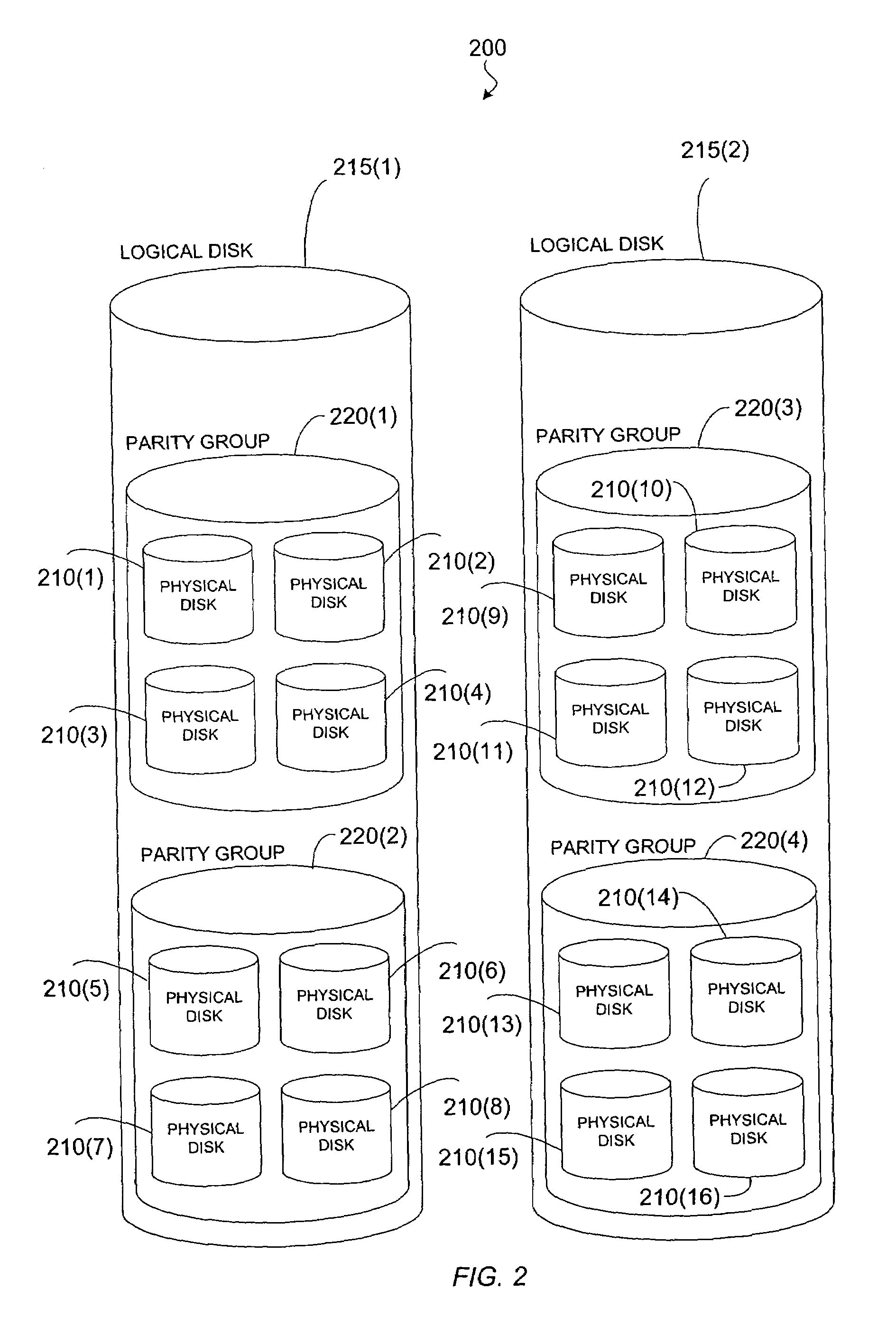
[0035]FIG. 2 is a simplified block diagram illustrating one embodiment of a storage system 200 according to the present invention. Particularly, FIG. 2 is a logical representation of a storage system 200 comprising a plurality of physical disk drives 210. The plurality of physical disks 210 are configured as one or more logical disks 215, and each logical disk 215 may comprise storage segments on one or more of the physical disks 210. But, as is well known to those skilled in the art, computers...


PUM


Abstract

A method of reallocating data among physical disks corresponding to a logical disk is provided. A logical disk is partitioned into a plurality of groups, each group comprising at least one segment on at least one of a first plurality of physical disks corresponding to the logical disk. One group of the plurality of groups is partitioned into a plurality of sub-groups, and, for each sub-group of the plurality of sub-groups but one, the sub-group is copied to at least one segment on at least one of a second plurality of physical disks corresponding to the logical disk.

Description

CROSS-REFERENCE TO RELATED APPLICATION[0001]This application is a continuation of application Ser. No. 09 / 905,270 filed Jul. 13, 2001 entitled “Storage Device with I / O Counter for Partial Data Reallocation,” now U.S. Pat. No. 6,647,460.BACKGROUND OF THE INVENTION[0002]The present invention relates generally to storage systems, and more specifically to storage systems having more than one physical disk configured as one logical disk.[0003]Redundant Array of Independent Disks (RAID) is a well-known technology that permits increased availability of data and also increased input / output (I / O) performance. In RAID storage systems, several physical disk drives are configured as one logical disk drive, and I / O requests to the logical disk drive are distributed within the storage system to the physical disk drives and processed in parallel. RAID technology provides many benefits. For example, a RAID storage system can accommodate very large file systems. Thus, large files and many files can ...

Claims


Application Information

Patent Timeline
Patent Type & Authority Patents(United States)
IPC IPC(8): G06F12/00G06F3/06
CPCG06F3/0613G06F11/1096G06F3/0689G06F3/065
Inventor KODAMA, SHOJI
Owner HITACHI LTD
Why Eureka
Try Eureka