Disk array system configuring a logical disk drive having a redundancy function

Inactive Publication Date: 2006-07-20
NEC CORP
View PDF15 Cites 18 Cited by
  • Summary
  • Abstract
  • Description
  • Claims
  • Application Information

AI Technical Summary

Benefits of technology

[0013] In accordance with the disk array system and the method of the present invention, the writing of the recovered data into a plurality of second physical disks in parallel reduces the time length n

Problems solved by technology

However, the redundancy configuration i

Method used


Image

  • Disk array system configuring a logical disk drive having a redundancy function
  • Disk array system configuring a logical disk drive having a redundancy function
  • Disk array system configuring a logical disk drive having a redundancy function

Examples


Embodiment Construction

[0019] Now, the present invention is more specifically described with reference to accompanying drawings, wherein similar constituent elements are designated by similar reference numerals throughout the drawings.

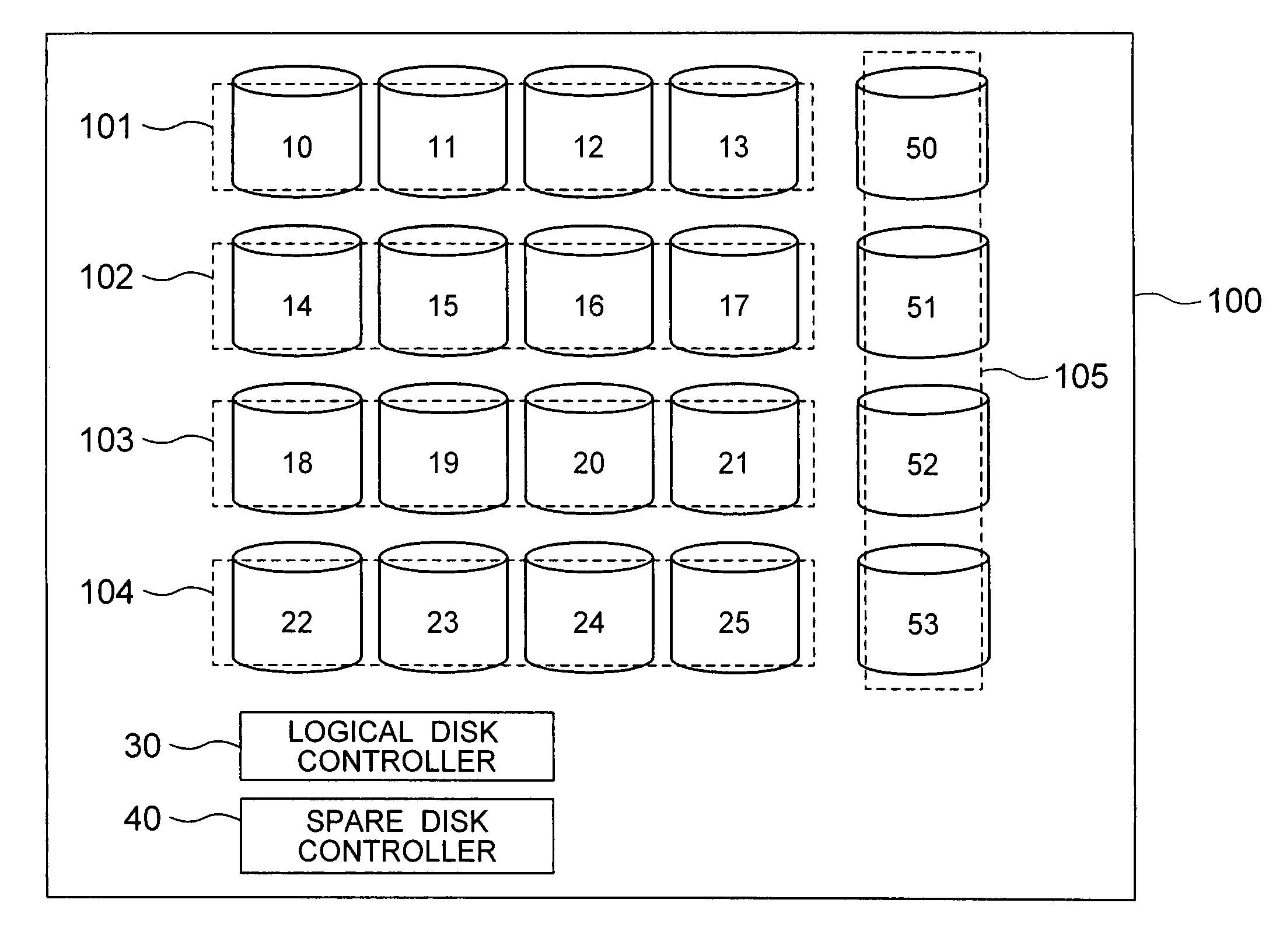
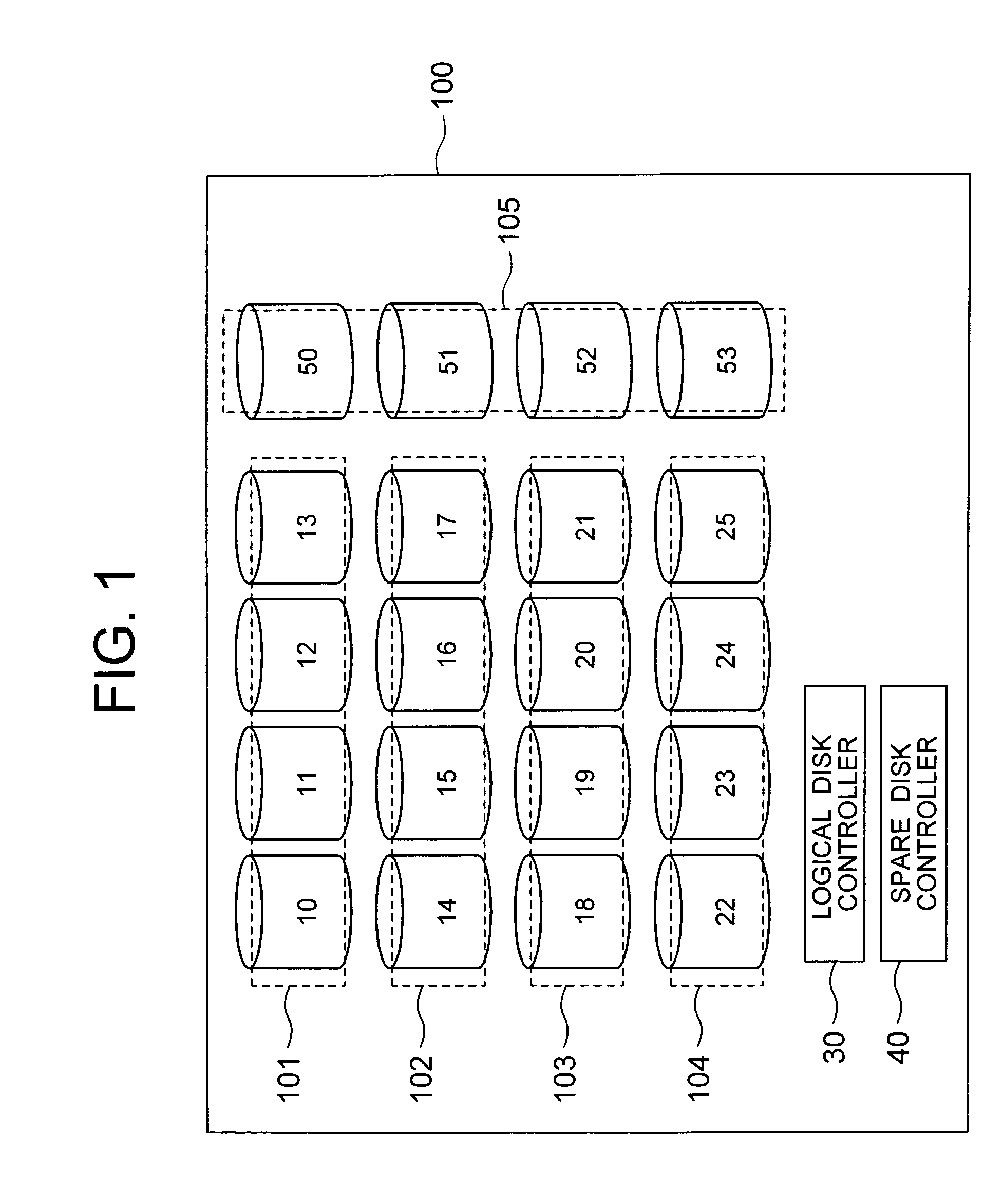
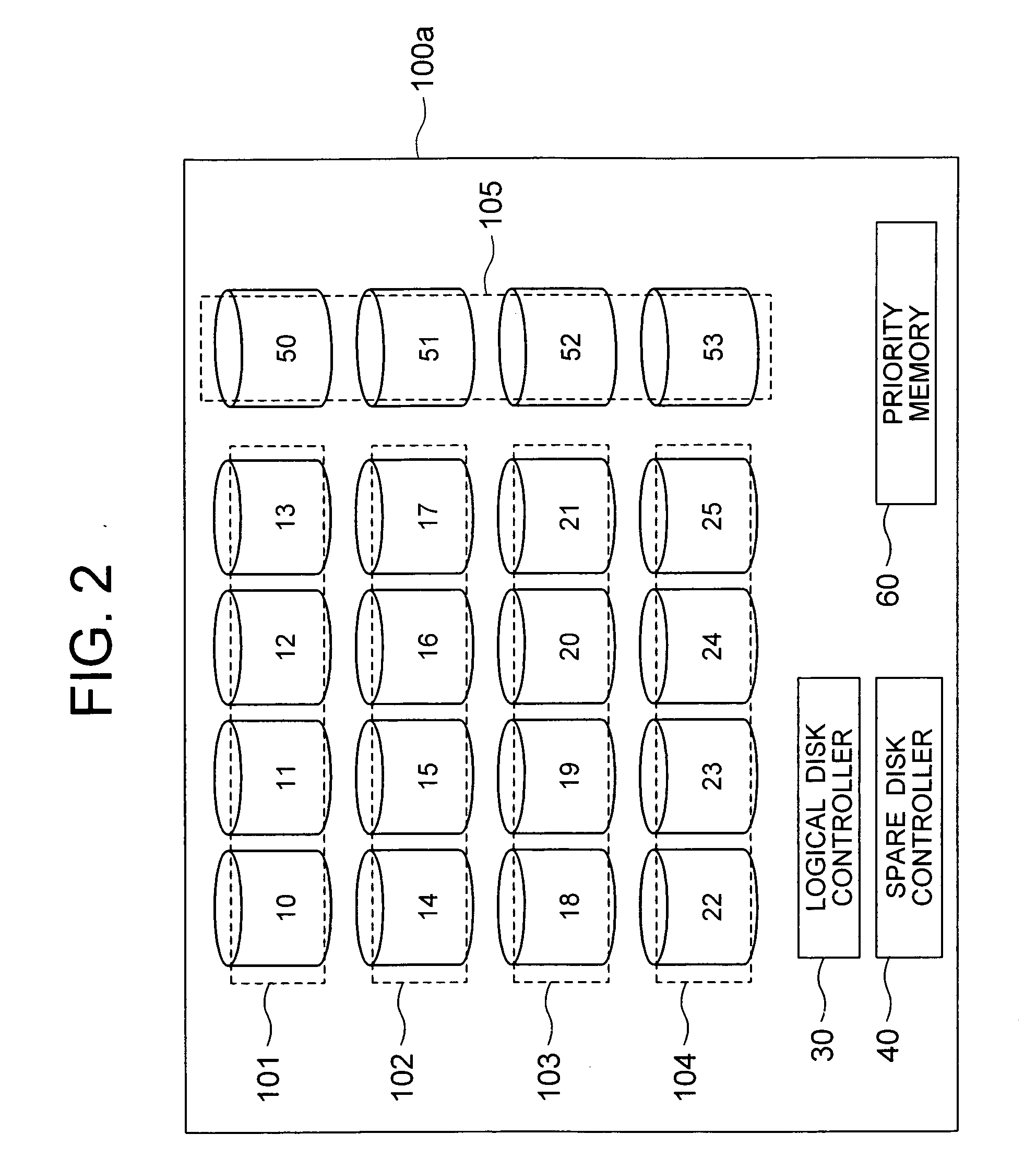
[0020]FIG. 1 shows a block diagram of a disk array system according to a first embodiment of the present invention. The disk array system generally designated by numeral 100 includes a plurality (16) of physical disks (first physical disks) 10 to 25, a plurality (4) of physical disks (second physical disks) 50 to 53, a logical disk controller 30, and a spare disk controller 40. The first logical disks 10 to 25 are used as main disks in the disk array system 100. The second logical disks 50 to 53 are used as spare disks. The second logical disks 50 to 53 have a lower read / write data rate compared to the first logical disks 10 to 25, and thus are less expensive.

[0021] The sixteen first physical disks 10 to 25 configure four logical disks 101 to 104. More specifically, the lo...


PUM


Abstract

A disk array system includes a plurality of physical disks (10 to 25) configuring a logical disk (101 to 104) having a redundancy function, and a plurality of spare disks (50 to 53) for storing recovered data recovered from the physical disks (10 to 25) by the redundancy function upon occurring of a failure of one of the logical disks (10 to 25). A spare disk controller (40) writes the recovered data into the spare disks (50 to 53) in parallel for a high-speed redundancy recovery.

Description

BACKGROUND OF THE INVENTION [0001] (a) Field of the Invention [0002] The present invention relates to a disk array system configuring a logical disk drive having a redundancy function, and more particularly, to a disk array system including a plurality of physical disk drives used as a single logical disk drive having a redundancy configuration. The present invention also relates to a method for use in such a disk array system. [0003] (b) Description of the Related Art [0004] A disk array system including a plurality of physical disk drives used as a single logical disk drive is known in the art. Hereinafter, a disk drive including a disk or disks is referred to as simply “disk” in this text. In the disk array system, data are generally stored in a redundancy technique for achieving no loss of data. Examples of this disk array system include a RAID (Redundant Array of Independent Disks) system. In the RAID system having a redundancy configuration, if a failure occurs in one of the p...

Claims


Application Information

Patent Timeline
IPC IPC(8): G11C29/00
CPCG06F11/1092G11B20/1803
Inventor SATO, HIROYUKI
Owner NEC CORP
Why Eureka
Try Eureka