Load bearing device including overboard indicator

a bearing device and indicator technology, applied in the direction of force/torque/work measurement apparatus, force measurement by elastic gauge deformation, instruments, etc., can solve the problems of chain or other lifting or load-bearing elongated device failure, other damage may be associated, etc., and achieve the effect of reducing thickness

Inactive Publication Date: 2006-04-25
CIT GRP BUSINESS CREDIT
View PDF24 Cites 13 Cited by
  • Summary
  • Abstract
  • Description
  • Claims
  • Application Information

AI Technical Summary

Benefits of technology

[0007]In preferred embodiments, a load bearing device of the present invention includes a safety loop interconnecting the first and second load bearing connectors so that a secondary load bearing alternative is provided if the overload indicator, which bears the load borne by the respective load bearing connectors, breaks, the safety loop will bear the load unless the load exceeds the load which can be borne by the safety loop. In other embodiments, the overload indicator is marked with a serial number to identify it. In preferred embodiments, a load bearing connector may also be marked with a serial number so that the overload indicator attached to the particular load bearing device made by the manufacturer can be correlated to help manufacturers determine whether the load bearing device has been manipulated by the consumer in any way to hide evidence of an excessive load exceeding the rated capacity of the load bearing device or the overload indicator.

Problems solved by technology

Chain and other lifting and load-bearing elongated devices such as rope, wire rope, cables, straps and the like are often used intentionally or unintentionally beyond their rated load-bearing capacity or working capacity.
When chain and the like are used in this way, and the rated capacity is exceeded, the chain or other lifting or load-bearing elongated devices may fail.
When the failure occurs, other damage may be associated with the event and, in certain circumstances, there are attempts to recover damages based upon liability associated with failure of the chain or other load bearing devices.
While devices that indicates load exist, these devices are relatively cumbersome and awkward to use or they are so expensive as to make use as an indicator of exceeded load bearing capacity impractical for commercial uses.
While load cells are a possibility, they are relatively expensive and the also require a source of electricity.
Incorporation of such an indication device into an elongated load-bearing device such as a rope, chain or other simple load bearing device is believed to be impractical unless the cost of such devices can be significantly reduced.

Method used


Image

  • Load bearing device including overboard indicator
  • Load bearing device including overboard indicator
  • Load bearing device including overboard indicator

Examples


example 1

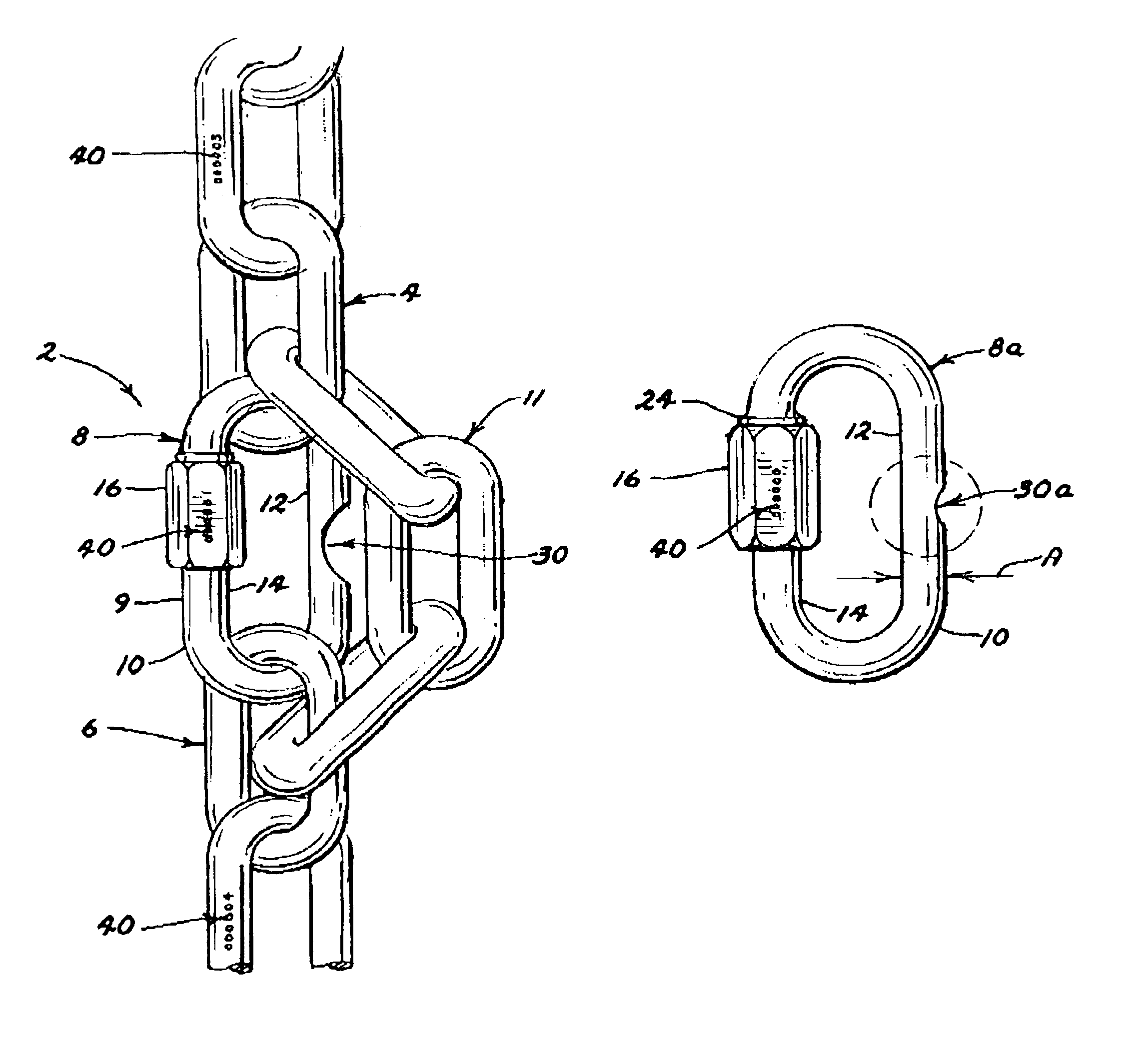
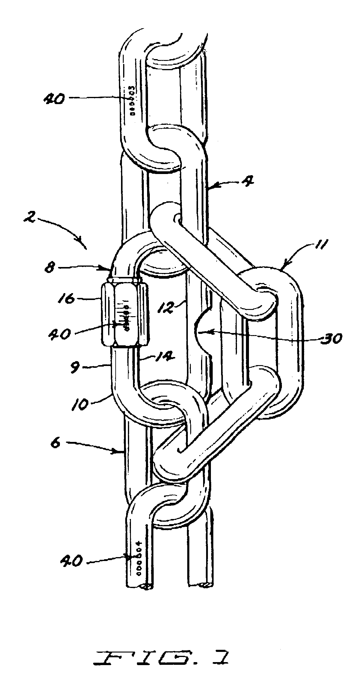
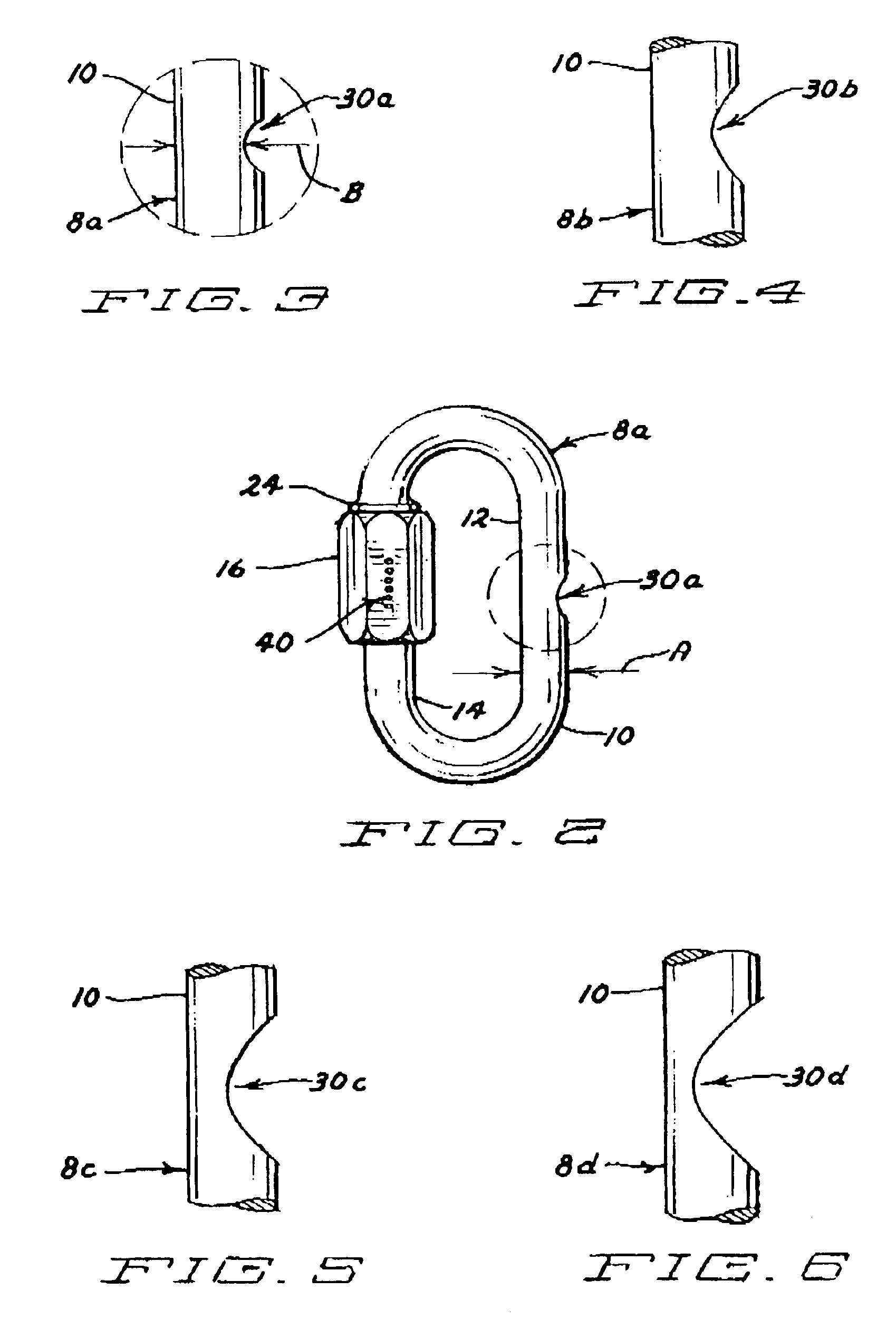
[0034]Quarter-inch commercially available quick links made from low carbon steel (SAE 1008 STEEL or the equivalent) were machined to create notches of various depths generally in the center of the side of the quick link opposite the connector to form overload indicators of the present invention. These modified quick link samples were incorporated into load bearing devices by connecting them to a 7MM grade 70 chain having a rated load bearing capacity of 3,150 pounds. The overload indicators were connected to the chain to become a load bearing component between two connecting links of separate load bearing connectors separated by three links of the chain that no longer bore the load and became the safety loop connected to the two connecting links of the load bearing connectors. The thickness of the remaining wire form material at the narrowest point at the bottom of the notch was measured using an optical comparator. The load bearing devices made with each of the respective overload ...

example 2

[0036]Quarter-inch commercially available quick links made from SAE 1008 steel were cut with a saw blade to create notches of various depths and to diminish the wire form material generally in the center of the side of the quick link opposite the connector to form overload indicators of the present invention. These modified quick link samples were incorporated into load bearing devices by connecting them to a 7MM grade 70 chain having a rated load bearing capacity of 3,150 pounds. The overload indicators were connected to the chain to become a load bearing component between two connecting links of separate load bearing connectors separated by three links of the chain that no longer bore the load and became the safety loop connected to the two connecting links of the load bearing connectors. The thickness of the remaining wire form material at the narrowest point at the bottom of the notch was measured using an optical comparator. The load bearing devices made with each of the respec...

example 3

[0038]Commercially available quarter-inch quick links made from SAE 1008 steel were drilled generally through the center of the wire opposite the connector on the quick link with a series of drill bits of various sizes to determine a predicted hole size (diameter) that would result in a break at a project load of 3,150 lbs. The actual hole size and the amount of remaining wire form material remaining on each side of the hole or opening were measured using an optical comparator. The peak load for each drilled quick link was measured by placing a continuously increasing load upon each drilled link sample using a Satec Tensile Strength Tester. The data for breaking strength was plotted against hole size to generate a best fit line showing the relationship between break strength and hole size. The correlation coefficient for the line relative to the data was determined to be 0.9470 which was believed to be acceptable. The equation for the line was y (break strength)=25,077x (hole diamet...


PUM

PropertyMeasurementUnit
diameteraaaaaaaaaa
diameteraaaaaaaaaa
load bearing capacityaaaaaaaaaa

Abstract

A load-bearing device including an overload indicator and a wire form overload indicator are provided for interconnection of load bearing connectors, preferably elongated load bearing connectors, for bearing a load. In preferred embodiments, the load bearing connectors are chains, ropes, wire ropes, cables, straps and the like, preferably chain. The wire form overload indicator preferably includes a wire form quick-link having a first thickness, and first and second elongated sides. The first elongated side preferably includes an interconnectable gap through which connection loops of the load bearing connectors can pass when the interconnectable gap is unconnected. The interconnectable gap includes a connection end and a connectable end, the connecting end having a connector capable of connecting the connecting end to the connectable end to close the gap. The second elongated side preferably has a portion having a diminished thickness as compared to the first thickness. The diminished thickness preferably has a predetermined load bearing capability and is calibrated to reduce the load bearing capability of the methods of making an overload indicator and a load bearing device including an overload indicator are also provided.

Description

[0001]This application claims benefit of provisional application 60 / 388,881 filed Jun. 14, 2002.BACKGROUND OF THE INVENTION[0002]Chain and other lifting and load-bearing elongated devices such as rope, wire rope, cables, straps and the like are often used intentionally or unintentionally beyond their rated load-bearing capacity or working capacity. When chain and the like are used in this way, and the rated capacity is exceeded, the chain or other lifting or load-bearing elongated devices may fail. When the failure occurs, other damage may be associated with the event and, in certain circumstances, there are attempts to recover damages based upon liability associated with failure of the chain or other load bearing devices. In these circumstances, it would be helpful to determine whether the rated load bearing capacity for the chain or other elongated load bearing device has been exceeded; if so, it is believed that the failure to stay within the rated load bearing capacity will prov...

Claims


Application Information

Patent Timeline
Patent Type & Authority Patents(United States)
IPC IPC(8): G01L1/26G01G23/00G01L5/10
CPCG01G23/005G01L5/102Y10S116/34
Inventor MCCAULEY, JOHN J.
Owner CIT GRP BUSINESS CREDIT
Why Eureka
Try Eureka