
Adjustable latching mechanism

a latching mechanism and adjustable technology, applied in the field of latching mechanisms, can solve the problems of difficult to completely unfold the table, damage to the support structure itself, and the operation of such tables, and achieve the effect of reducing the number of times the table is opened and closed

Inactive Publication Date: 2006-04-25
PALMER HAMILTON
View PDF34 Cites 6 Cited by
  • Summary
  • Abstract
  • Description
  • Claims
  • Application Information

AI Technical Summary

Benefits of technology

[0010]Another object of this invention is to provide a novel latching mechanism that is easily adjustable and yet highly reliable in operation.
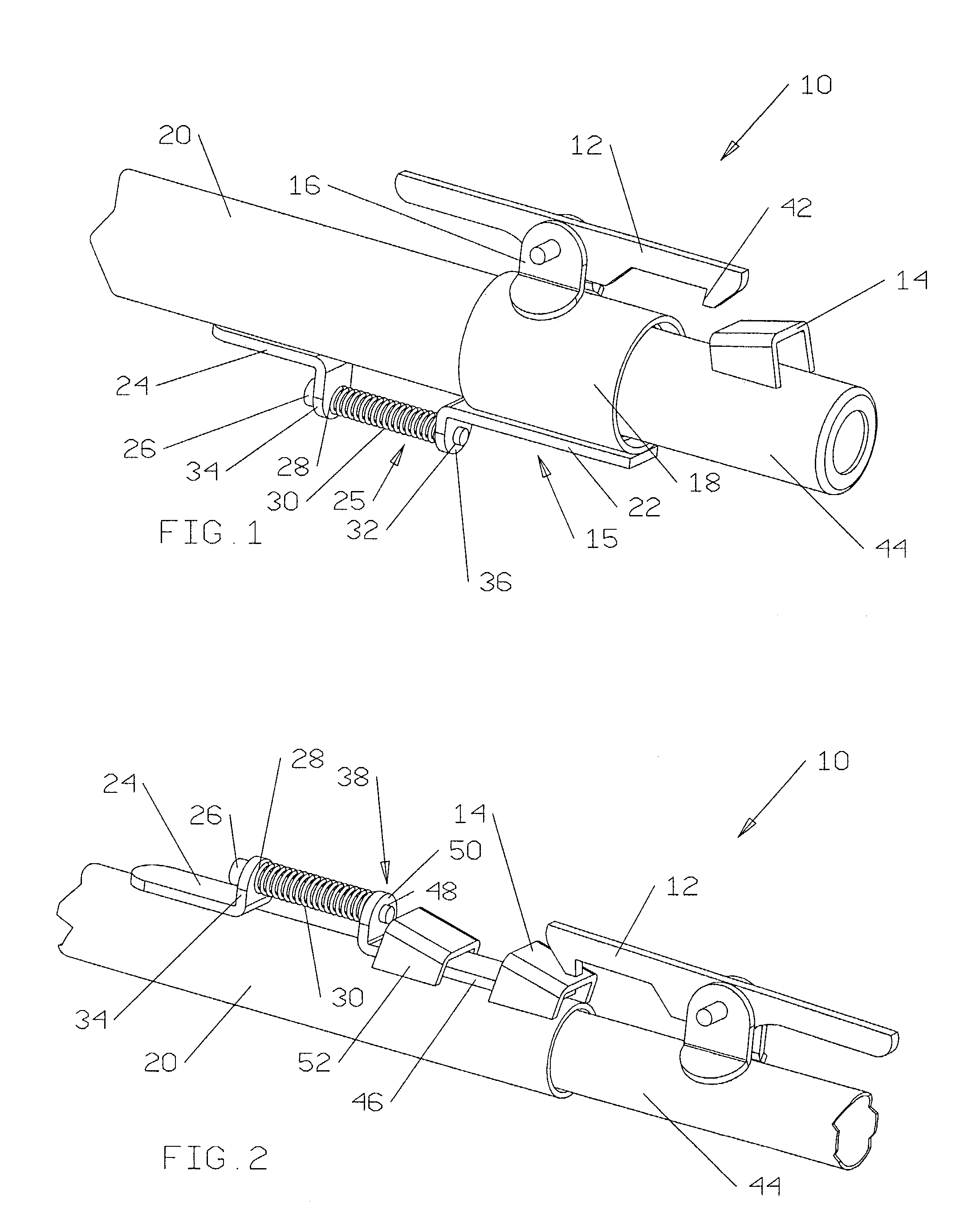
[0022]A most preferred embodiment finds the latching comprised of an adjustment-bracket mounted to the first center-leg member, a catch-bracket slidably attached to the first center-leg member, a catch mounted to the catch bracket, an adjustment mechanism connecting the adjustment-bracket to the catch-bracket, and a latch mounted to the second center-leg member in registry with the catch. In this configuration, the catch can be extended and retracted along the first center-leg member between certain limits so as to allow it to achieve many different positions where it can be engaged by the latch.

Problems solved by technology

This poses a number of problems in the operation of such tables over time.
One such problem is that a rise or bump in the floor beneath the center leg support so that it is elevated in comparison to the surface beneath the outer leg supports may make it difficult to completely unfold the table so as to activate the lock or latch present on the center support.
Even if the user is successful in forcefully triggering the lock, the effort required can cause stress and oftentimes damage to the support structure itself as well as to any cap or other covering placed over the base of the support.
In addition, given the unevenness found on most floors, repeated use of the table on such a surface will leave numerous holes or indentations where contact is made between the center leg support and the various elevated regions.
These problems will continue unless a way is found by the user to either make an adjustment in the manner in which the support is held in place by the latching mechanism or identify those areas on a given floor over which the table should not be erected.
Moreover, even these solutions have limited value since unfolding the table at a different spot in the school or church might require yet another readjustment.

Method used


Image

  • Adjustable latching mechanism
  • Adjustable latching mechanism
  • Adjustable latching mechanism

Examples


Embodiment Construction

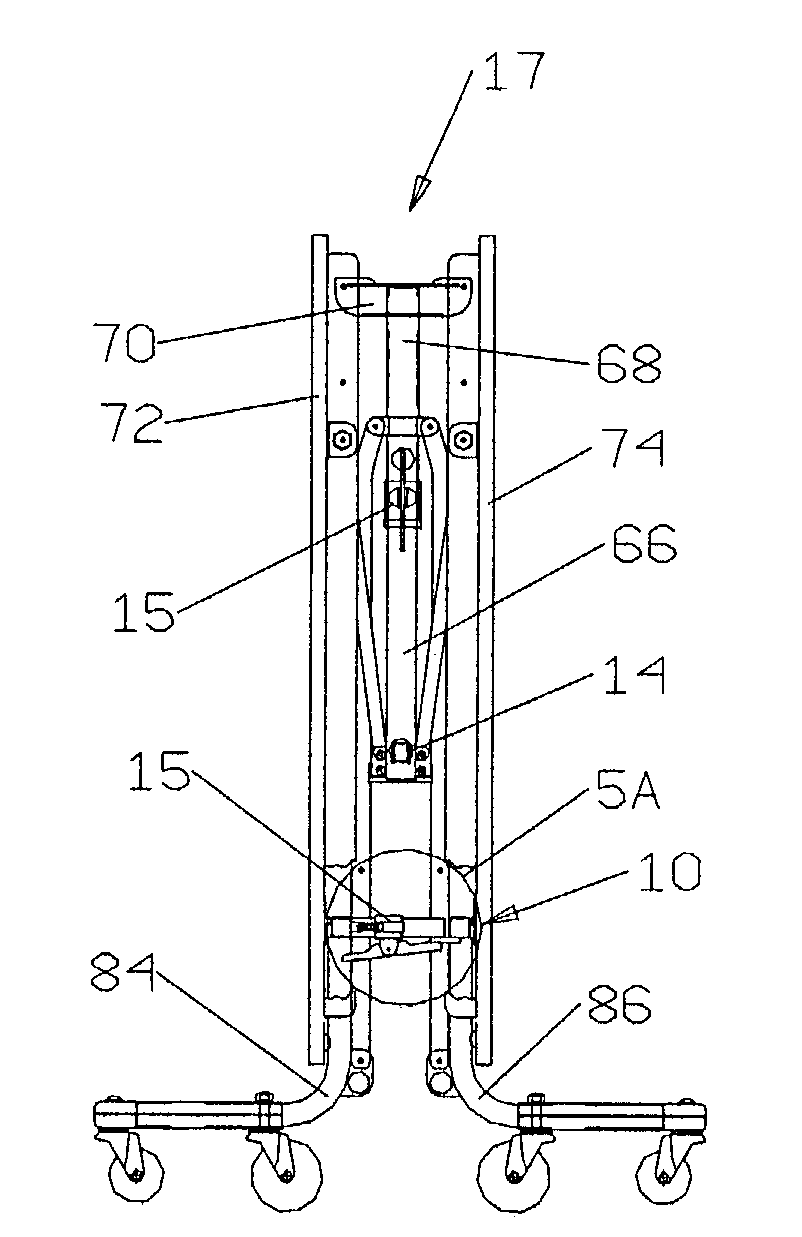
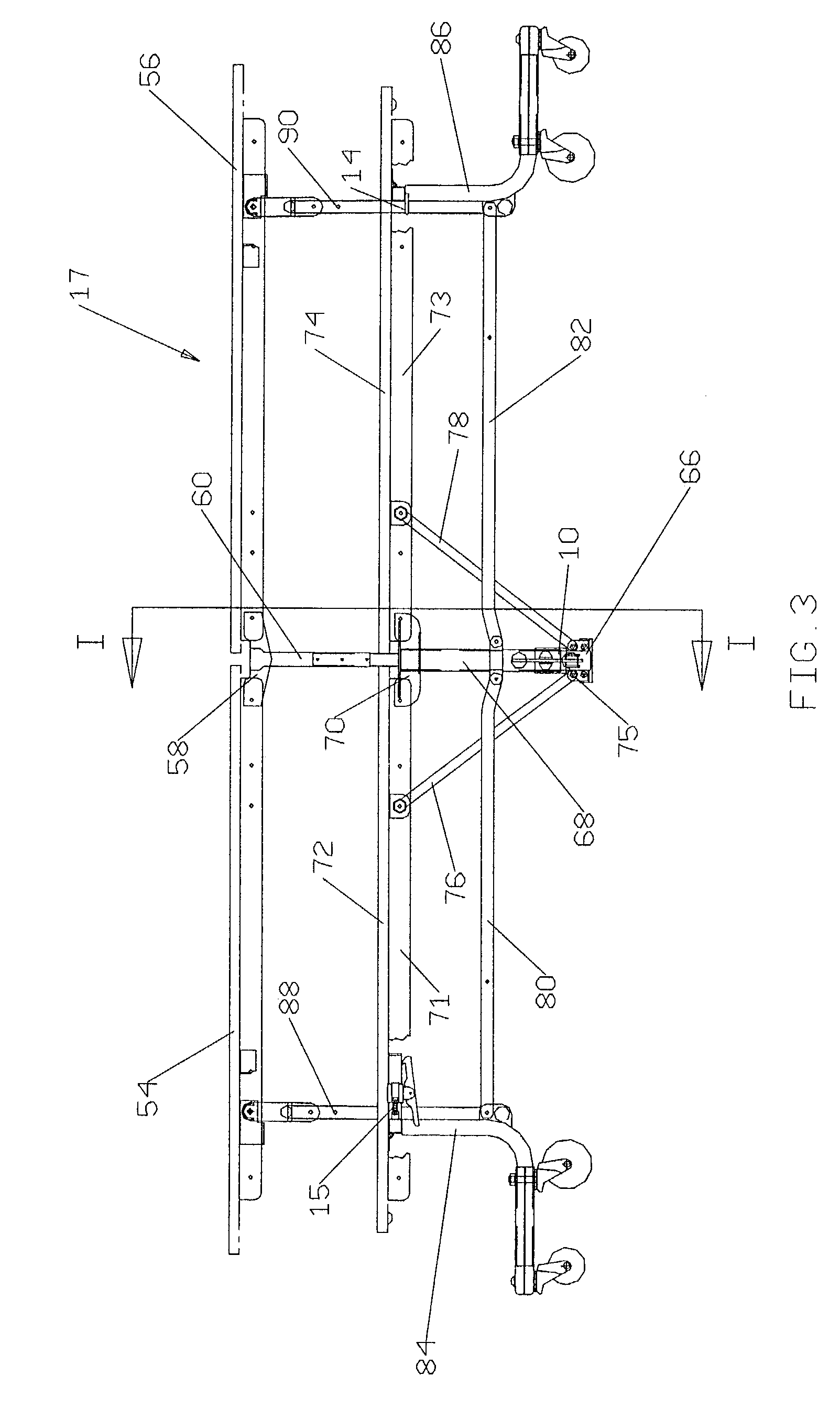
[0030]The drawings illustrate a latching mechanism 10 in accordance with this invention. One preferred embodiment is particularly shown in FIG. 1.

[0031]Referring to FIGS. 1 and 3, latching mechanism 10 includes a latch 12 and a catch 14. Latch 12 is pivotally attached to a latch-support 16 so as to allow either end of latch 12 to swing upward or downward with respect to latch-support 16. Latch 12 is provided with a beak portion 42 on the end facing catch 14. A torsion spring (not shown) is attached between latch 12 and latch-support 16 so as to bias beak portion 42 in a downward direction.

[0032]Latch 12 and latch-support 16 are part of an adjustable latch assembly 15 attached to a first leg support member 20 on an institutional folding table 17. Latch-support 16 is rigidly secured to a collar 18 that freely circumscribes first leg support member 20. A latch-bracket 22 is rigidly attached to collar 18 at a location apart from latch-support 16 and in an orientation whereby the length ...


PUM


Abstract

An adjustable latching mechanism for securing together first and second leg support members on an institutional folding table. The latching mechanism comprises a first latching member slidably mounted to the first leg support member and a second latching member mounted to the second leg support member. The first latching mechanism can be extended and retracted between limits so as to permit a multiplicity of positions where the second latching member can engage the first latching member. The first latching member may either be an adjustable latch or an adjustable catch. The latching mechanism is preferably used on a center leg support to maintain the table in a substantially unfolded position.

Description

FIELD OF THE INVENTION[0001]This invention is related generally to latching mechanisms and, more particularly, to adjustable latching mechanisms for institutional folding tables.BACKGROUND OF THE INVENTION[0002]Institutional tables of the type that can be folded for storage and then unfolded for use are commonly found in schools and churches across the country. These tables will often have a table top comprised of two sections hinged together as well as being oftentimes joined to bench or stool seating. The supporting structure for many of these tables will include a center leg support and two outer leg supports.[0003]The center leg support is comprised of an upper member and a lower member wherein the lower member is capable of telescopically collapsing within the upper member. The center leg support is mechanically connected to the table top sections and seating sections in such a manner that when the table is folded, the lower member is free to separate from the upper member by m...

Claims


Application Information

Patent Timeline
IPC IPC(8): A47B5/00
CPCA47B25/003
Inventor PAJERSKI, FRANCIS L.
Owner PALMER HAMILTON
Learn More