
Connector

a technology of connecting rods and connectors, applied in the direction of incorrect coupling prevention, coupling device connection, electrical equipment, etc., can solve the problem of loud noise of collision

Inactive Publication Date: 2006-04-25
SUMITOMO WIRING SYST LTD
View PDF3 Cites 27 Cited by
  • Summary
  • Abstract
  • Description
  • Claims
  • Application Information

AI Technical Summary

Benefits of technology

The invention is a connector with two housings that are locked together using a resiliently deformable lock arm. The lock arm creates an aerial vibration when it collides with the housing, and a resonance space is provided to amplify the collision sound. The resonance space is exposed at the outer surface of the connector, allowing the collision sound to efficiently reach the operator's ears. The oscillating portion, which is continuous with the lock, creates a large aerial vibration when it is restored resiliently, making the collision sound louder. An enclosed space is defined at the side of the oscillating portion opposite from the resonance space, further amplifying the collision sound.

Problems solved by technology

Thus, the collision sound is loud.

Method used


Image

  • Connector
  • Connector
  • Connector

Examples


Embodiment Construction

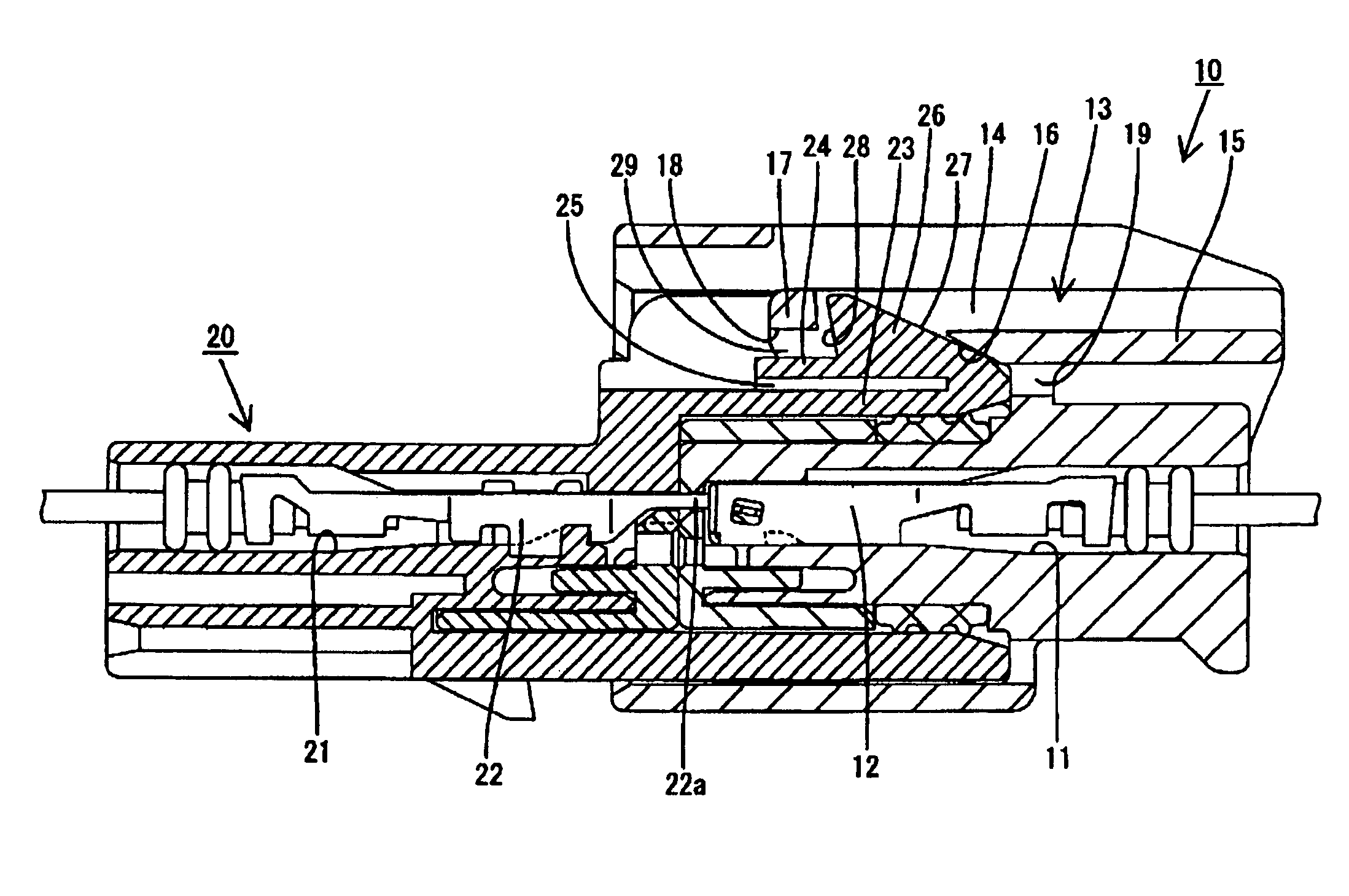
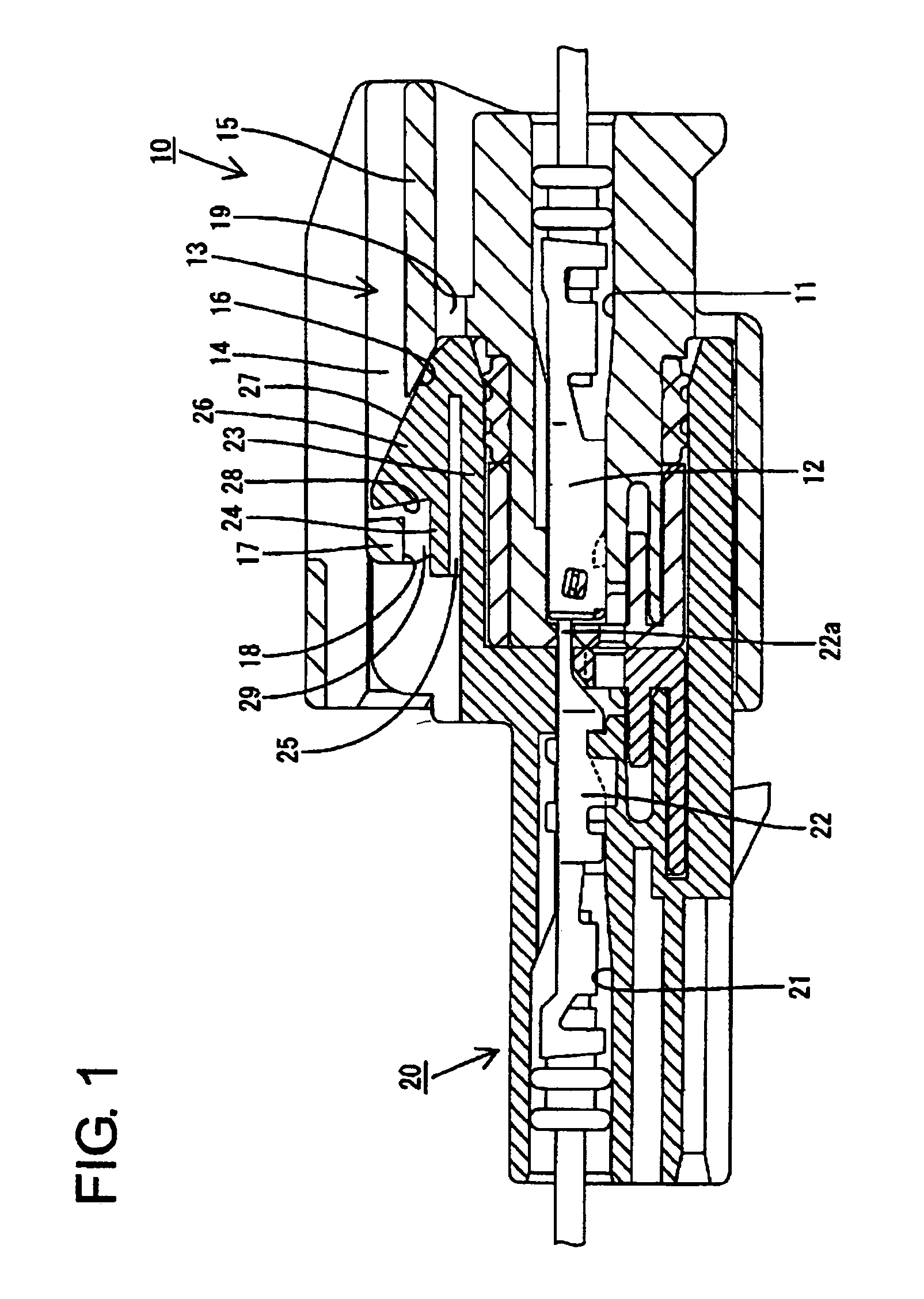
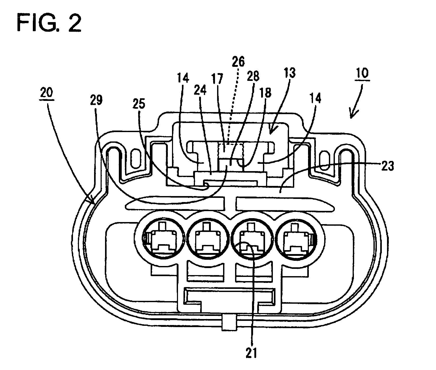
[0018]A connector according to the invention includes first and second housings 10 and 20, as shown in FIGS. 1 to 6. The first housing 10 is made of a synthetic resin and is transversely symmetrical. Cavities 11 are formed transversely side-by-side and penetrate the first housing 10 in forward and backward directions, and female terminal fittings 12 are accommodated in the respective cavities 11. A lock arm 13 is formed integrally on the upper surface of the first housing 10 and extends longitudinally in forward and backward directions. The terms upper and lower are used herein to provide a convenient frame of reference, but are not intended to imply a required gravitational orientation The lock arm 13 has left and right side walls 14 and a coupling 15 that couples both sidewalls 14. The left and right sidewalls 14 are narrow and long in forward and backward directions and have a vertically long rectangular lateral cross section. The bottom edges of both sidewalls 14 are narrow and ...


PUM


Abstract

A second housing (20) is formed with an oscillating portion (24) for creating an aerial vibration by the collision with a resiliently restored lock arm (13) and a resonance space (25) for causing the aerial vibration created by the oscillating portion (24) to resonate. When the lock arm (13) is resiliently restored, the aerial vibration created by the oscillating portion (24) upon the collision with the lock arm (13) resonates in the resonance space (25), and a collision sound of the lock arm (13) and the oscillating portion (24) is amplified by this resonance.

Description

BACKGROUND OF THE INVENTION[0001]1. Field of the Invention[0002]The present invention relates to a connector.[0003]2. Description of the Related Art[0004]Japanese Unexamined Patent Publication No. 2003-45567 discloses a connector with first and second housings that can be connected together. The first housing has a lock arm and the second housing has a lock. The lock arm resiliently deforms and passes the lock in the process of connecting the two housings. The lock arm then returns resiliently to engage the lock when the two housings are connected properly.[0005]The lock arm collides with the second housing during the resiliently restoration, and creates an audibly detectable snapping sound. The operator relies upon this audible snapping sound as indication of complete mating.[0006]The resilient-restoring force of the lock arm is small. Thus, the lock arm collides with the second housing with a weak force and a soft collision sound. As a result, it is difficult for the operator to r...

Claims


Application Information

Patent Timeline
Patent Type & Authority Patents(United States)
IPC IPC(8): H01R3/00H01R13/64H01R13/641H01R13/639
CPCH01R13/641
Inventor NIMURA, KAZUHIKO
Owner SUMITOMO WIRING SYST LTD
Learn More