Balanced device characterization including test system calibration

a balanced device and test system technology, applied in the direction of measurement devices, resistance/reactance/impedence, instruments, etc., can solve the problems of unfavorable balanced device operation, single-ended s-parameters measured by the conventional vna that may not accurately reflect the performance of balanced devices, and unwanted oscillations, etc., to facilitate the measurement of mixed mode s-parameters

Inactive Publication Date: 2006-04-25
KEYSIGHT TECH
View PDF9 Cites 43 Cited by
  • Summary
  • Abstract
  • Description
  • Claims
  • Application Information

AI Technical Summary

Problems solved by technology

Unfortunately, most conventional multiport VNAs measure multiport devices having single-ended (i.e., non-differential) ports.
Unfortunately, many balanced devices behave differently in response to a single-ended stimulus signal such as those generated by a conventional multiport VNA than to a true differential stimulus signal.
Therefore, the single ended S-parameters measured by the conventional VNA may not accurately reflect a performance of the balanced device in the presence of a differential stimulus signal.
In a worst case, the balanced device may even fail to operate (e.g., become unstable resulting in unwanted oscillations) or be damaged when presented with a single-ended stimulus signal.
However, such specialized VNA systems either omit portions of the system during a calibration or employ specialized calibration standards and methods.
Omitting portions of the system during calibration may lead to errors that are unacceptably high for many practical applications.
Specialized calibrations standards may be difficult to construct and / or characterize with sufficient accuracy to support an acceptable level of calibration.
Moreover, using specialized VNA systems with or without specialized calibration standards for measuring a balanced device often may be prohibitively expensive.

Method used


Image

  • Balanced device characterization including test system calibration
  • Balanced device characterization including test system calibration
  • Balanced device characterization including test system calibration

Examples


Embodiment Construction

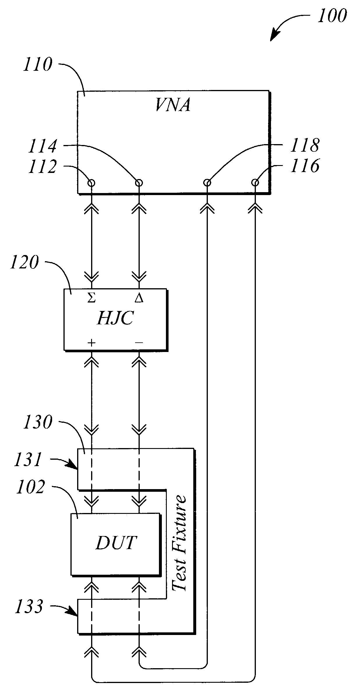
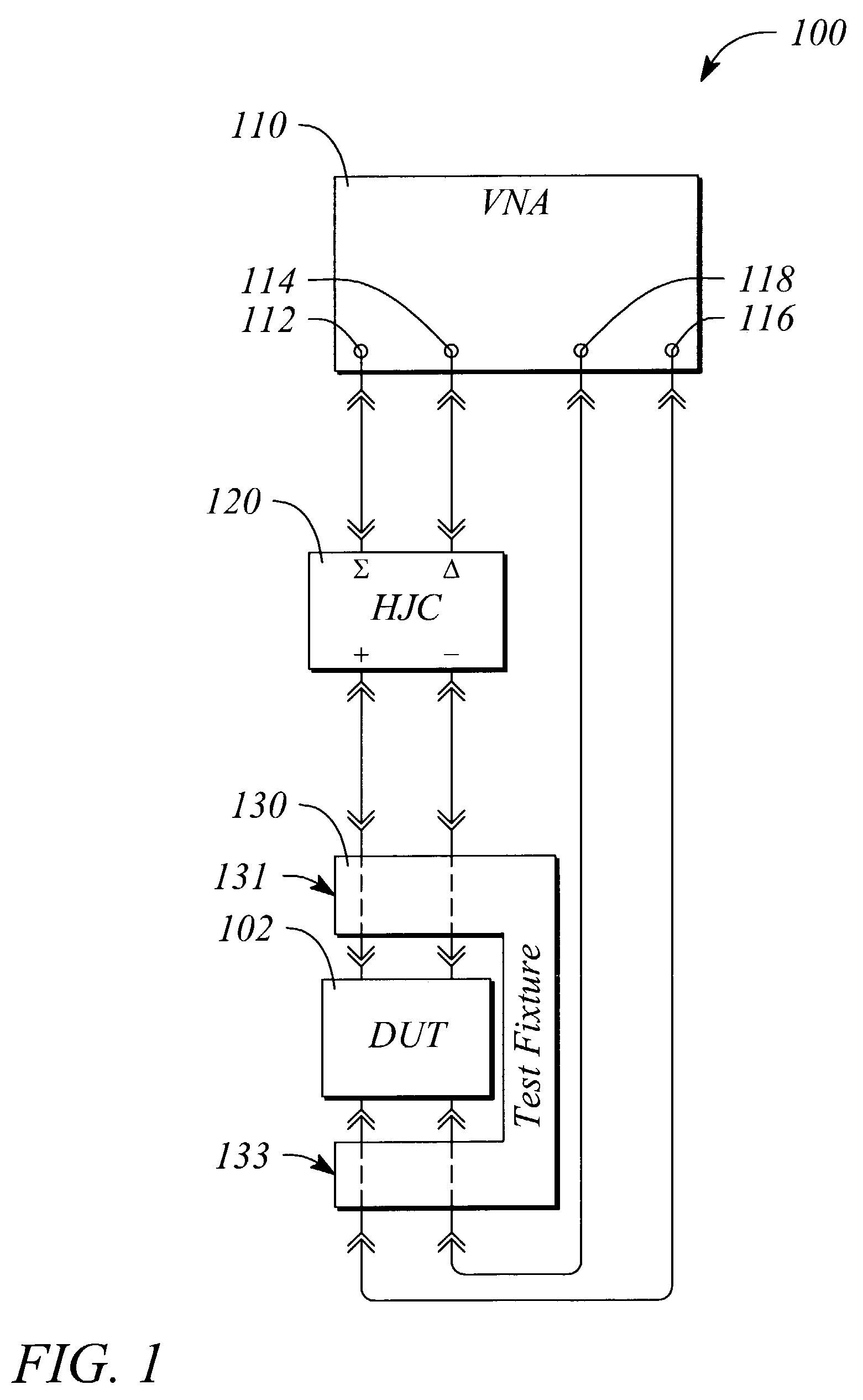
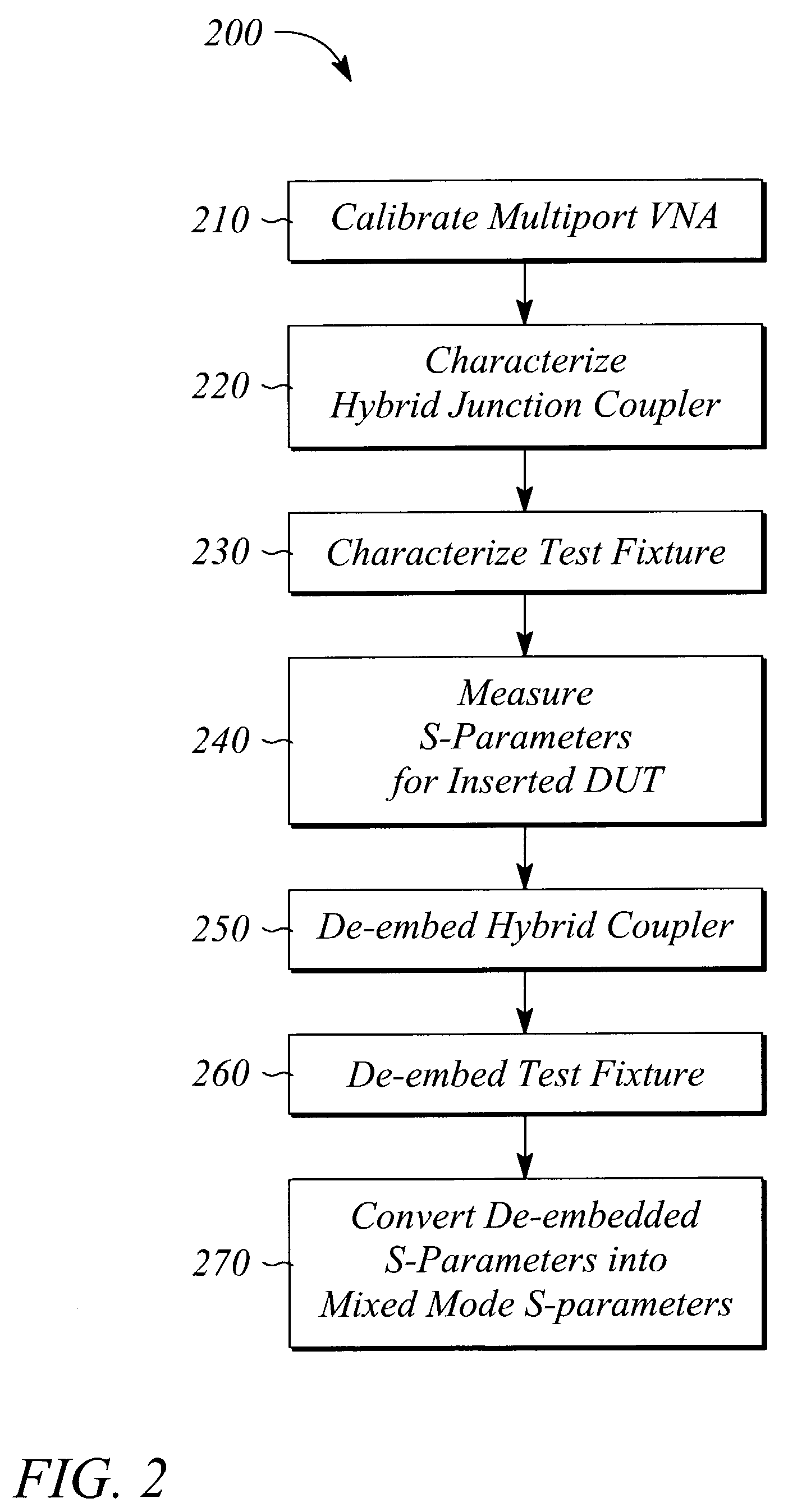
[0017]FIG. 1 illustrates a block diagram of a multiport vector network analyzer (VNA) measurement system 100 for balanced device characterization according to an embodiment of the present invention. The multiport VNA measurement system 100 comprises a multiport VNA 110, a hybrid junction coupler 120, and a test fixture 130. The hybrid junction coupler 120 is connected between a pair of ports of the VNA 110 and a pair of input ports of the test fixture 130. Output ports of the test fixture 130 are connected to other ports of the multiport VNA 110. The test fixture 130 is adapted to hold and interface to a device under test (DUT) 102. In some embodiments, the test fixture 130 is omitted and the DUT 102 is connected between an output of the hybrid junction coupler 120 and the other ports of the multiport VNA.

[0018]In general, the DUT 102 is a balanced device having a differential input and a differential output. In some cases the DUT 102 may have one or more non-differential inputs and...


PUM


Abstract

A test system and method characterize a balanced device under test (DUT) with a vector network analyzer (VNA) measurement system using a differential or balanced stimulus signal and further calibrate the VNA using conventional calibration standards. An effect of errors introduced by an uncalibrated portion of the measurement system, such as test fixturing and hybrid junction coupling, is de-embedded from measured S-parameters for the DUT. The method includes calibrating the VNA, characterizing the uncalibrated portion, measuring S-parameters for the DUT with the calibrated VNA, and de-embedding the uncalibrated portion characterization from the S-parameter measurements. The test system includes a multiport VNA measurement system that includes a hybrid coupler, an optional test fixture, and a computer program. A processor executes the computer program. Instructions of the computer program implement the method.

Description

TECHNICAL FIELD[0001]The invention relates to test and measurement equipment. In particular, the present invention relates to measuring balanced devices using a vector network analyzer.BACKGROUND ART[0002]Balanced devices operating at high frequencies including, but not limited to, microwave frequencies are becoming more and more prevalent in modem systems, especially communication systems. Concomitant with the use of such devices comes a need to measure a performance of the devices. As with single-ended (i.e., non-balanced) microwave devices, balanced microwave devices may be characterized using S-parameters. However, in the case of balanced devices, so-called ‘mixed mode’ S-parameters are generally used to characterize the device instead of the more conventional or single-ended S-parameters. Mixed mode S-parameters relate differential and common mode signals applied to ports of the balanced device to differential and common mode responses at the ports.[0003]A multiport vector netw...

Claims


Application Information

Patent Timeline
Patent Type & Authority Patents(United States)
IPC IPC(8): G01R27/00G01R27/32G01R27/28G01R35/00
CPCG01R27/32G01R35/005
Inventor ANDERSON, KEITH F.
Owner KEYSIGHT TECH
Why Eureka
Try Eureka