Multiplexer for adjacent NTSC and DTV channels

a multi-channel and adjacent technology, applied in the field ofapparatus and a multiplexing method of signals of different frequency bands, can solve the problems of high cost, serious disadvantage of signal combiners, and nil reflected energy to channel inputs

Inactive Publication Date: 2004-03-23
GSLE SUBCO L L C
View PDF14 Cites 26 Cited by
  • Summary
  • Abstract
  • Description
  • Claims
  • Application Information

AI Technical Summary

Problems solved by technology

These signal combiners have a serious disadvantage in that they do not present a constant impedance to the inputs that receive the signals.
Although reflected energy to the channel inputs is nil, the cost is high because 2N hybrids are required, where N is the number of signals or channels to be multiplexed.
Moreover, the bandwidth is limited to the short circuit VSWR (voltage standing wave ratio) of the output hybrid.
In coax hybrids, the amplitude balance is controlled in the design of the hybrid by the use of multiple quarter wave coupled sections, which are power limited.
In wave guide hybrids, which can take more power, the amplitude balance is limited by the inability to produce multiple quarter wave coupled sections.

Method used


Image

  • Multiplexer for adjacent NTSC and DTV channels
  • Multiplexer for adjacent NTSC and DTV channels
  • Multiplexer for adjacent NTSC and DTV channels

Examples


Embodiment Construction

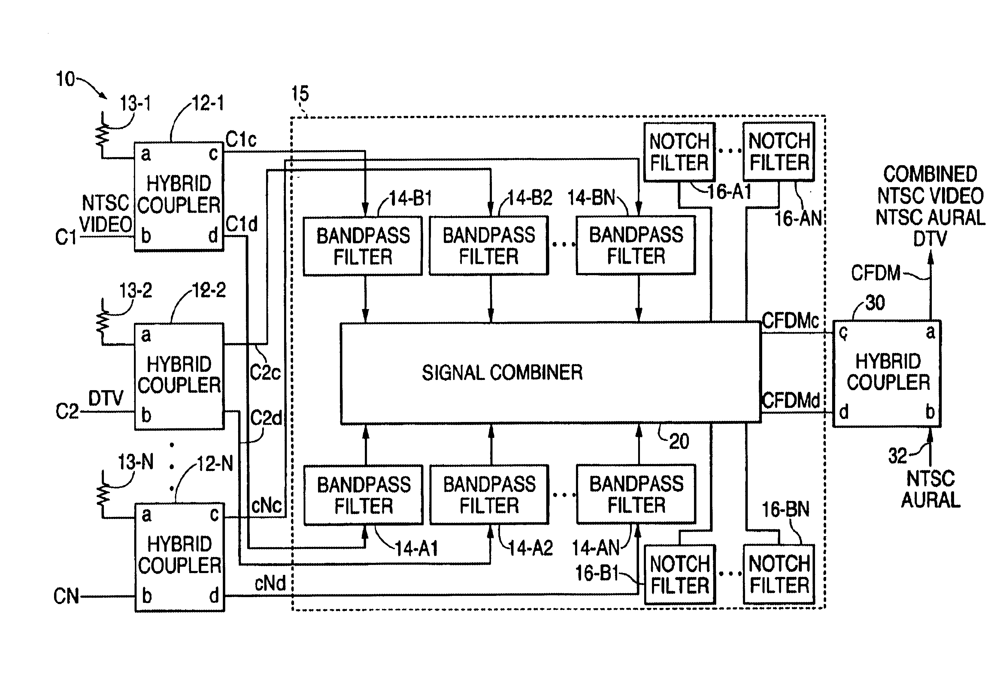
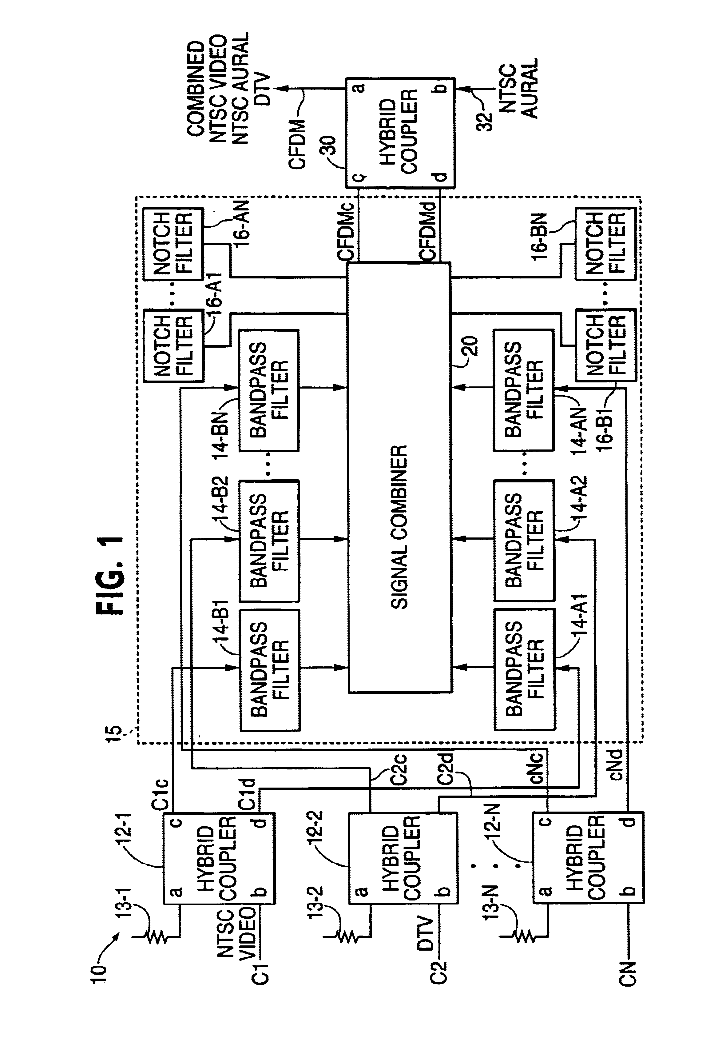
Referring to FIG. 1, there is shown a multiplexer 10 according to the present invention. Multiplexer 10 includes N input hybrid couplers 12-1 and 12-2 through 12-N, where N is two or more, a filtering and combining system 15 and an output coupler 30 for a total of N+1 hybrid couplers. Hybrid couplers 12-1, 12-2 and 12-N receive input signals C1, C2 and CN, respectively. Signals C1, C2 and CN each have frequencies in a different frequency band or channel (channels 1 through N, respectively) and constitute the signals to be multiplexed by multiplexer 10 to a frequency division multiplexed output signal CFDM at output hybrid coupler 30.

According to the present invention, the signals of adjacent frequency channels are the NTSC and DTV versions of the same image or picture. For example, channels 1 and 2 may be channels 30 and 31 with their signals C1 and C2 being in NTSC and DTV format, respectively.

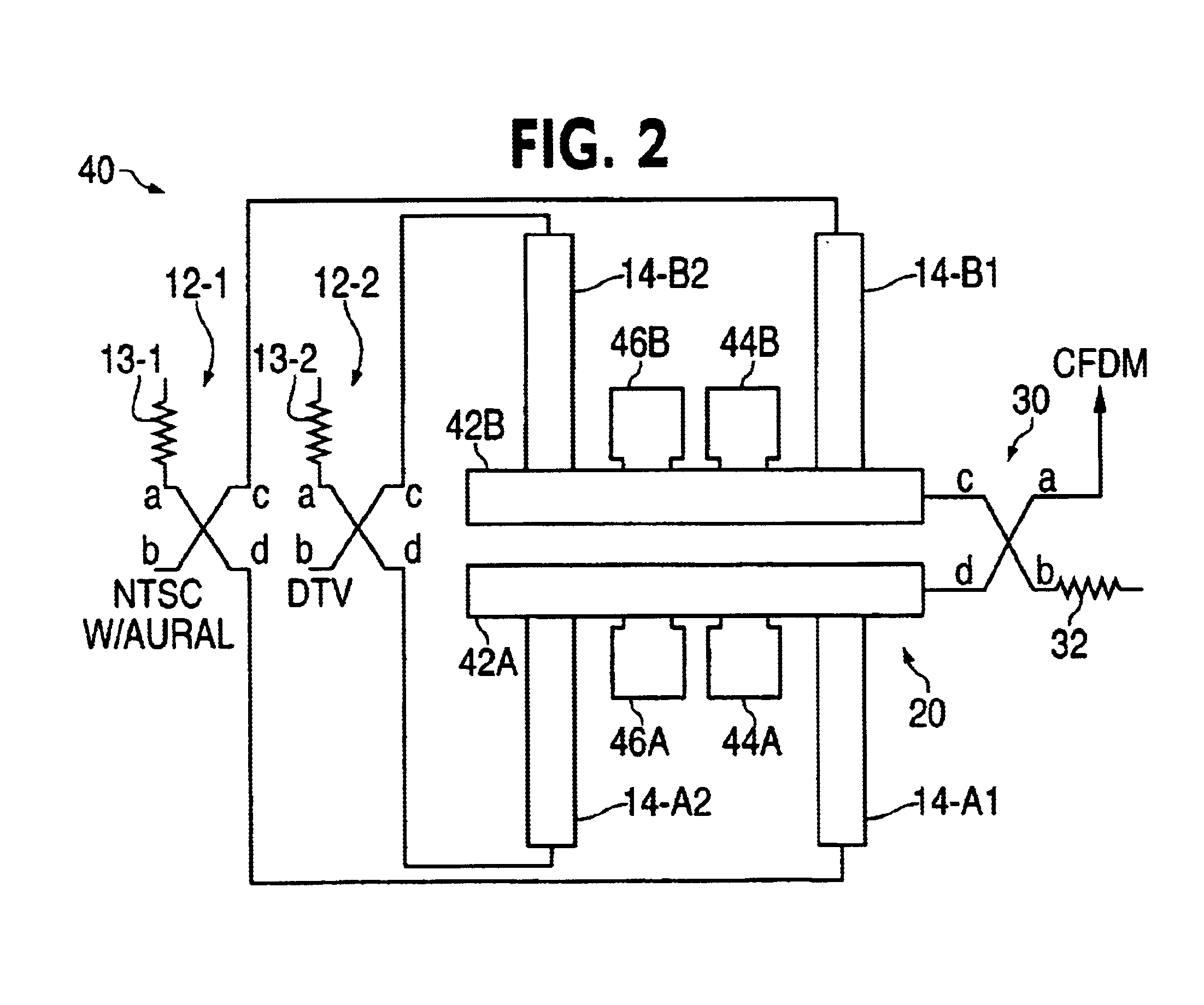
Hybrid couplers 12-1 through 12-N and 30 are substantially identical and have ports a, b,...


PUM


Abstract

A signal mutiplexer that combines the NTSC and DTV signals of adjacent television channels into a composite signal for transmission on a common transmission line or wave guide. Separate hybrid couplers and band pass filters produce quadrature phase signals that are combined in a signal combiner to produce a pair of quadrature phase multiplexed signals. A notch filter reflects the aural component of the NTSC signal. An output hybrid coupler combines the pair of multiplexed quadrature phase signals with the reflected aural component to produce the composite signal.

Description

1. Field of the InventionThis invention relates to an apparatus and a method for multiplexing signals of different frequency bands, and, in particular, to a low cost signal multiplexer and method that combines a national standard television code ("NTSC") signal with a digital television ("DTV") signal.2. Description of the Prior ArtThe introduction of digital television service has resulted in a need for a station to broadcast the television picture in the NTSC format for reception by television sets that are not equipped for digital reception and in DTV format for reception by television sets that are equipped for digital reception. These stations have been allocated the next higher channel for DTV service. That is, the NTSC signal is broadcast on channel N and the DTV signal is broadcast on channel N+1, channels N and N+1 being adjacent channels. There is a need for these stations to combine the NTSC and DTV signals into a composite signal for transmission on a common transmission...

Claims


Application Information

Patent Timeline
Patent Type & Authority Patents(United States)
IPC IPC(8): H01P1/213H01P1/20H04N5/38H04N11/00
CPCH01P1/2138H04N5/38H04N11/004H04N11/26
Inventor GRANDCHAMP, BRETT J.DECORMIER, WILLIAM A.
Owner GSLE SUBCO L L C
Why Eureka
Try Eureka