Phased array antenna system with adjustable electrical tilt

a phased array antenna and electrical tilt technology, which is applied in the direction of antennas, direction finders, transmission, etc., can solve the problems of increasing the level of the side lobe, increasing the cost and complexity of the antenna, and compromising system performance, so as to achieve the effect of adjusting the electrical tilt and extending the electrical tilt rang

Inactive Publication Date: 2008-11-11
QUINTEL CAYMAN LTD
View PDF60 Cites 28 Cited by
  • Summary
  • Abstract
  • Description
  • Claims
  • Application Information

AI Technical Summary

Benefits of technology

[0026]The invention provides the advantage that it is possible to adjust electrical tilt for the whole array using only a single variable phase shifter, instead of one variable phase

Problems solved by technology

These requirements are mutually conflicting: for example, increasing the boresight gain may increase the level of the side lobes.
Whereas an antenna's angle of mechanical tilt may be adjusted by repositioning its radome, changing its angle of electrical tilt requires additional electronic circuitry which increases antenna cost and complexity.
The need for an individual angle of electrical tilt from a shared antenna has hitherto not been met and has resulted in compromises in system performance.
Further reductions in system performance may al

Method used


Image

  • Phased array antenna system with adjustable electrical tilt
  • Phased array antenna system with adjustable electrical tilt
  • Phased array antenna system with adjustable electrical tilt

Examples


Embodiment Construction

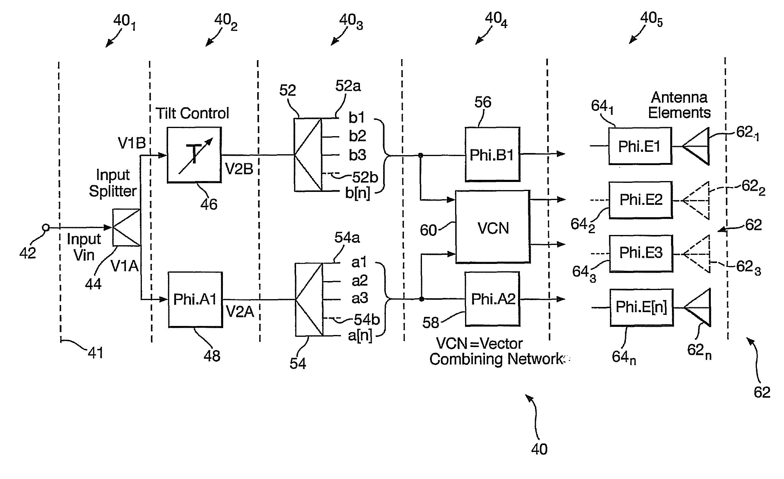
[0063]All examples illustrated employ connections for which source impedances of signals are equal to respective load impedances in order to form a ‘matched’ system. A matched system maximises the power transmitted from a source to a load and avoids signal reflections. Where signal lines are terminated in a resistor (see e.g. FIG. 6) the value of the resistor is equal to the system impedance in order to form a matched termination.

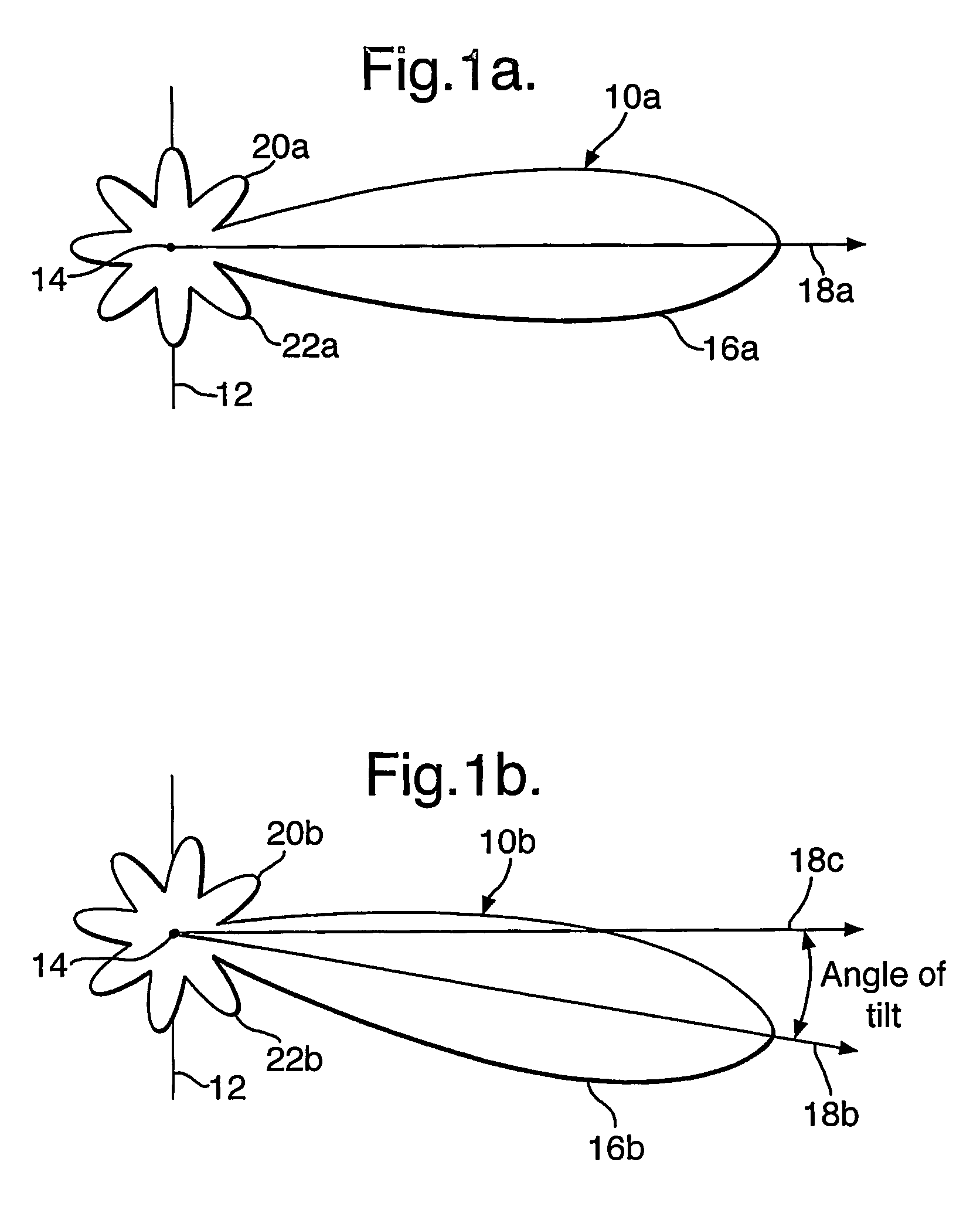
[0064]Referring to FIG. 1, there are shown vertical radiation patterns (VRP) 10a and 10b of an antenna 12 which is a phased array of individual antenna elements (not shown). The antenna 12 is planar, has a centre 14 and extends vertically in the plane of the drawing. The VRPs 10a and 10b correspond respectively to zero and non-zero variation in delay or phase of antenna element signals with distance across the antenna 12. They have respective main lobes 16a, 16b with centre lines or “boresights”18a, 18b, first upper sidelobes 20a, 20b and first lower sidelo...


PUM


Abstract

A phased array antenna system with adjustable electrical tilt includes an array (62) of antenna elements 621, to 6210. It has a splitter (44) dividing a radio frequency (RF) carrier signal into two signals between which a phase shifter (46) introduces a variable phase shift. Further splitters (52) and (54) divide the relatively phase shifted signals into two sets of five signals. Four of each of the sets of five signals are vectorially combined in a network of 180 degree hybrid couplers 601, to 604. This provides vector sum and difference components which together with the fifth members of the sets are fed to respective fixed phase shifters (56, 58) and 641, to 6410. The phase shifters 641, to 6410 provide signals which are appropriately phased for use as phased array drive signals for respective antenna elements 621, to 6210. Adjustment of the single phase shift provided by the variable phase shifter (46) changes the angle of electrical tilt of the entire antenna array (62).

Description

BACKGROUND OF THE INVENTION[0001](1) Field of the Invention[0002]The present invention relates to a phased array antenna system with adjustable electrical tilt. It is suitable for use in many areas of telecommunications but finds particular application in cellular mobile radio networks, commonly referred to as mobile telephone networks. More specifically, but without limitation, the antenna system of the invention may be used with second generation (2G) mobile telephone networks such as the GSM system, and third generation (3G) mobile telephone networks such as the Universal Mobile Telephone System (UMTS).[0003](2) Description of the Art[0004]Operators of cellular mobile radio networks generally employ their own base-stations, each of which has at least one antenna. In a cellular mobile radio network, the antennas are a primary factor in defining a coverage area in which communication to the base station can take place. The coverage area is generally divided into a number of overlap...

Claims


Application Information

Patent Timeline
IPC IPC(8): H01Q3/00H04B1/00H04M1/00H01Q1/24H01Q3/36H01Q3/40H01Q21/00
CPCH01Q1/246H01Q3/36H01Q3/40H01Q21/0006H01Q3/26H01Q1/24
Inventor HASKELL, PHILIP EDWARD
Owner QUINTEL CAYMAN LTD
Why Eureka
Try Eureka