

Diplexer synthesis using composite right/left-handed phase-advance/delay lines
a phase-advance/delay line and composite technology, applied in the field of diplexers, can solve the problems of time-consuming process of parameter optimization of the three-port junction connecting the filter and the requisite performance tuning, and achieve the effect of high level of agreemen
- Summary
- Abstract
- Description
- Claims
- Application Information
AI Technical Summary
Benefits of technology
Problems solved by technology
Method used
Image

Examples
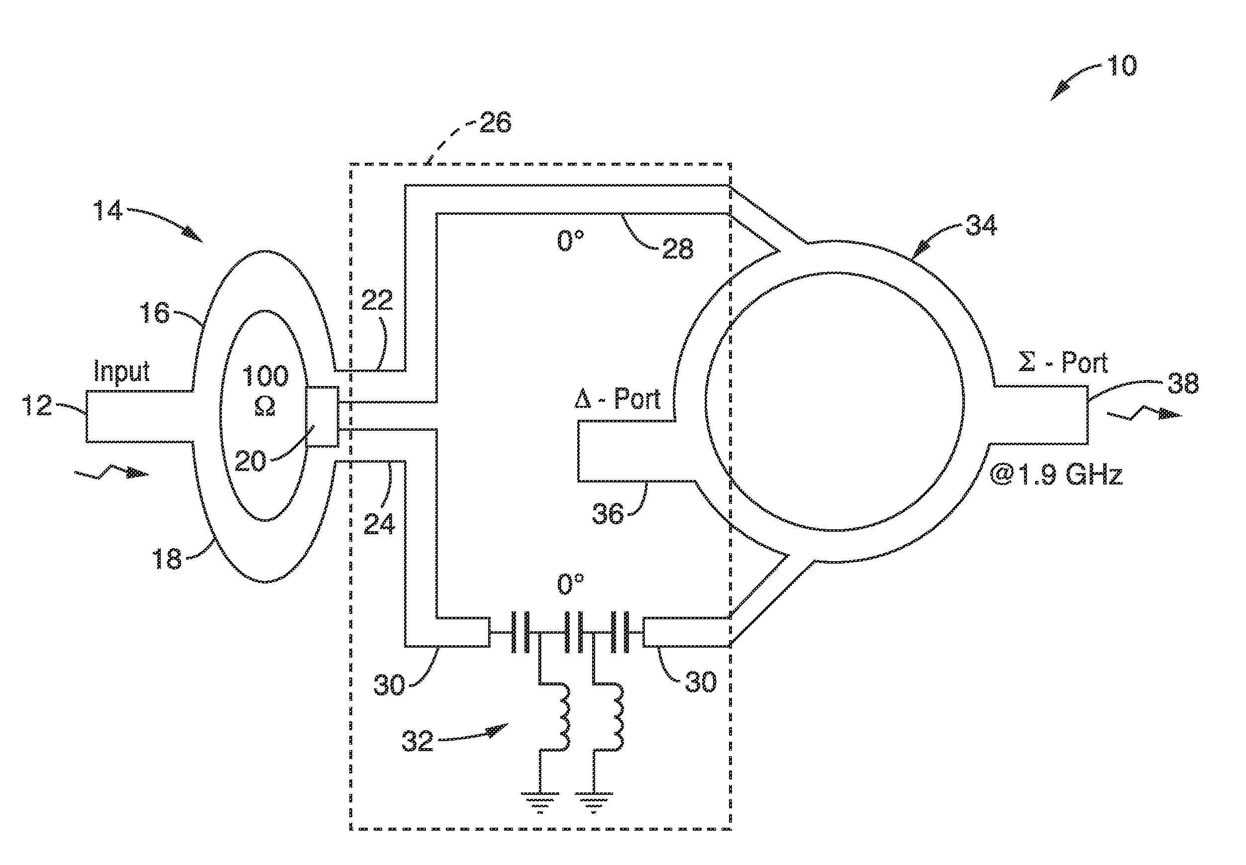
embodiment 10
[0056]Delay line 32 is configured with CRLH transmission structures to provide arbitrary dual-band operation, and is designed to have (0°, −180°) phase responses at a first and second operating frequency. The example implementation of embodiment 10 depicts a diplexer designed for a first frequency of 1.9 GHz and a second frequency of 2.4 GHz, and a characteristic impedance of 50 Ω.
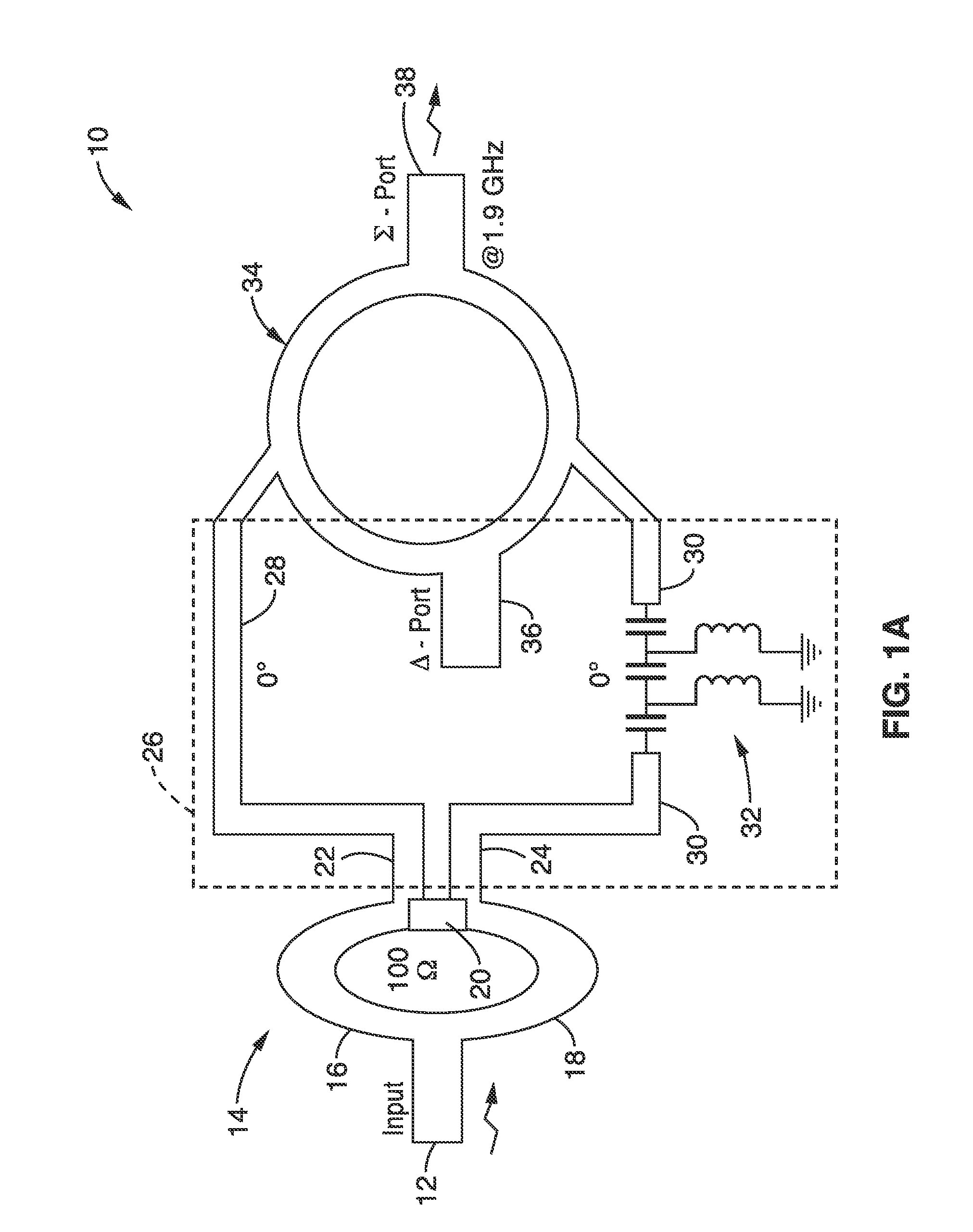
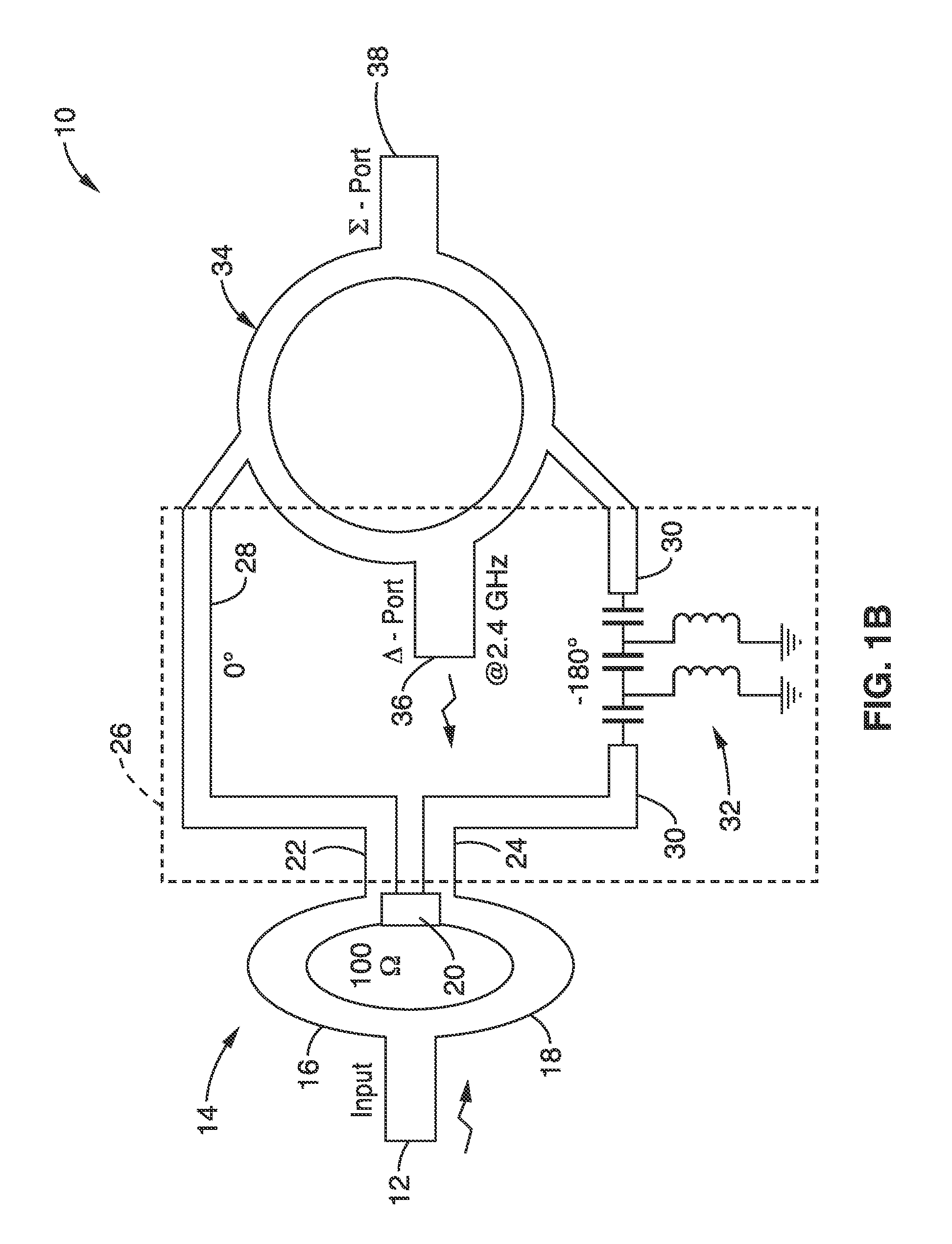
[0057]As shown in FIG. 1A, at 1.9 GHz the phase progression along two paths of the delay line are identical, which helps signal construction at the Σ port 38. On the other hand, the anti-phase signals from the delay line cause signals at 2.4 GHz to appear at the Δ port 36 as indicated in FIG. 1B. Therefore, the frequency selective mechanism is achieved.
[0058]The phase nonlinearity and controllability of the CRLH structures allow arbitrary dual-band operation while keeping the diplexer structure compact. At least one embodiment of the invention can be implemented using a single-band 180° hybrid for diplexin...
embodiment 1
[0079]2. An apparatus , wherein said apparatus comprises a diplexer.
[0080]3. An apparatus according to embodiment 1, wherein said power divider is configured as a three-port junction outputting said first signal and said second signal which are in phase with each other with equal frequency makeup and at substantially equal power.
[0081]4. An apparatus according to embodiment 1, wherein said power divider comprises a Wilkinson power divider.
[0082]5. An apparatus according to embodiment 1, wherein said phase delay line is configured for introducing a first phase delay or advance at the first operating frequency ƒ1, and a second phase delay or advance at the second operating frequency ƒ2.
[0083]6. An apparatus according to embodiment 1, wherein said CRLH hybrid coupler comprises composite right / left-handed (CRLH) transmission line (TL) material having both right-handed (RH) and left-handed (LH) portions.
[0084]7. An apparatus according to embodiment 1, wherein said CRLH hybrid coupler co...
embodiment 16
[0094]17. An apparatus , wherein said CRLH phase delay line is configured for providing a first phase delay at the first operating frequency ƒ1, and a second phase delay at the second operating frequency ƒ2, and in which the first phase delay and the second phase delay are not equal.
[0095]18. An apparatus according to embodiment 16, wherein dual frequency characteristics of each transmission line (TL) segment of said CRLH hybrid coupler arise in response to an anti-parallel relationship between phase and group velocities below a transition frequency ω0, within left-handed (LH) material within the CRLH hybrid coupler, and a parallel relationship between phase and group velocities above transition frequency ω0 within the right-handed material (RH) within the CRLH hybrid coupler.
[0096]19. An apparatus for diplexing an input signal, comprising: a power divider configured for splitting an input signal into a first signal and a second signal which are in phase with each other having equal...
PUM
 Abstract
Description
Claims
Application Information