Methods and apparatus for cooling turbine engine combustor exit temperatures

a technology of combustor exit temperature and cooling turbine engine, which is applied in the direction of mechanical equipment, machines/engines, lighting and heating apparatus, etc., can solve the problems of difficult to achieve and the combustors may only receive limited dilution air

Inactive Publication Date: 2006-05-02
GENERAL ELECTRIC CO
View PDF16 Cites 42 Cited by
  • Summary
  • Abstract
  • Description
  • Claims
  • Application Information

AI Technical Summary

Problems solved by technology

Within at least some known recuperated gas turbine engines, cooling requirements of turbines may create a pattern factor requirement at the combustor that may be difficult to achieve because of combustor design characteristics associated with recuperated gas turbine engines.
However, because of cooling considerations downstream from the combustor and because of the limited number and relative orientation of such impingement and dilution openings, such combustors may only receive only limited dilution air from such openings.

Method used


Image

  • Methods and apparatus for cooling turbine engine combustor exit temperatures
  • Methods and apparatus for cooling turbine engine combustor exit temperatures
  • Methods and apparatus for cooling turbine engine combustor exit temperatures

Examples


Embodiment Construction

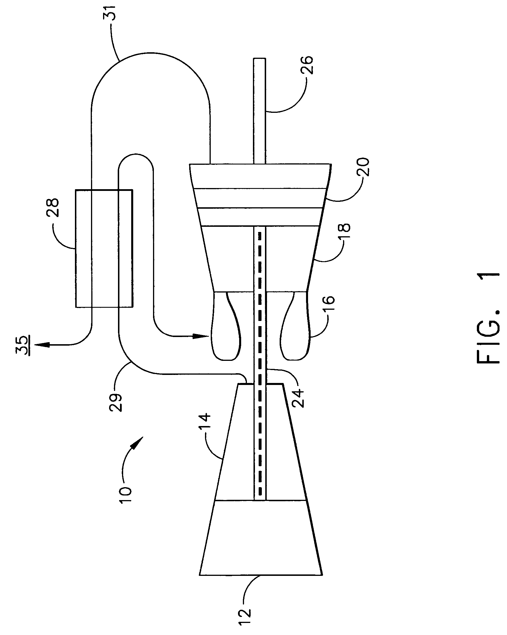
[0013]FIG. 1 is a schematic illustration of a gas turbine engine 10 including a compressor 14, and a combustor 16. Engine 10 also includes a high pressure turbine 18 and a low pressure turbine 20. Compressor 14 and turbine 18 are coupled by a first shaft 24, and turbine 20 drives a second output shaft 26. Shaft 26 provides a rotary motive force to drive a driven machine, such as, but, not limited to a gearbox, a transmission, a generator, a fan, or a pump. Engine 10 also includes a recuperator 28 that has a first fluid path 29 coupled serially between compressor 14 and combustor 16, and a second fluid path 31 that is serially coupled between turbine 20 and ambient 35. In one embodiment, the gas turbine engine is an LV100 engine available from General Electric Company, Cincinnati, Ohio. In the exemplary embodiment, compressor 14 is coupled by a first shaft 24 to turbine 18, and powertrain and turbine 20 are coupled by a second shaft 26.

[0014]In operation, air flows through high press...


PUM


Abstract

A method facilitates assembling a combustor for a gas turbine engine. The method comprises coupling an inner liner to an outer liner such that a combustion chamber is defined therebetween, positioning an outer support a distance radially outward from the outer liner, and positioning an inner support a distance radially inward from the inner liner. The method also comprises forming at least two rows of impingement openings extending through at least one of the inner support and the outer support for channeling impingement cooling air therethrough towards at least one of the inner liner and the outer liner, and forming at least one row of dilution openings extending through at least one of the inner liner and the outer liner for channeling dilution cooling air therethrough into the combustion chamber

Description

STATEMENT REGARDING FEDERALLY SPONSORED RESEARCH OR DEVELOPMENT[0001]The U.S. Government may have certain rights in this invention pursuant to contract number DAAE07-00-C-N086.BACKGROUND OF THE INVENTION[0002]This invention relates generally to gas turbine engines, more particularly to combustors used with gas turbine engines.[0003]Known turbine engines include a compressor for compressing air which is suitably mixed with a fuel and channeled to a combustor wherein the mixture is ignited for generating hot combustion gases. At least some known combustors include an inner liner that is coupled to an outer liner such that a combustion chamber is defined therebetween. Additionally, an outer support is coupled radially outward from the outer liner such that an outer cooling passage is defined therebetween, and an inner support is coupled radially inward from the inner liner such that an inner cooling passage is defined therebetween.[0004]Within at least some known recuperated gas turbin...

Claims


Application Information

Patent Timeline
Patent Type & Authority Patents(United States)
IPC IPC(8): F23R3/04F02C7/18F23R3/00F23R3/06
CPCF23R3/002F23R3/06F23R2900/03044
Inventor HOWELL, STEPHEN JOHNDANIS, ALLEN MICHAEL
Owner GENERAL ELECTRIC CO
Why Eureka
Try Eureka