Desk system
a desk and desk technology, applied in the field of desk systems, can solve the problems of inconvenient assembly of built-up work desks, high labor intensity, and inability to meet the needs of users, and achieve the effect of easy assembly and recombined, and quick adjustment to the changes
- Summary
- Abstract
- Description
- Claims
- Application Information
AI Technical Summary
Benefits of technology
Problems solved by technology
Method used
Image
Examples
first embodiment
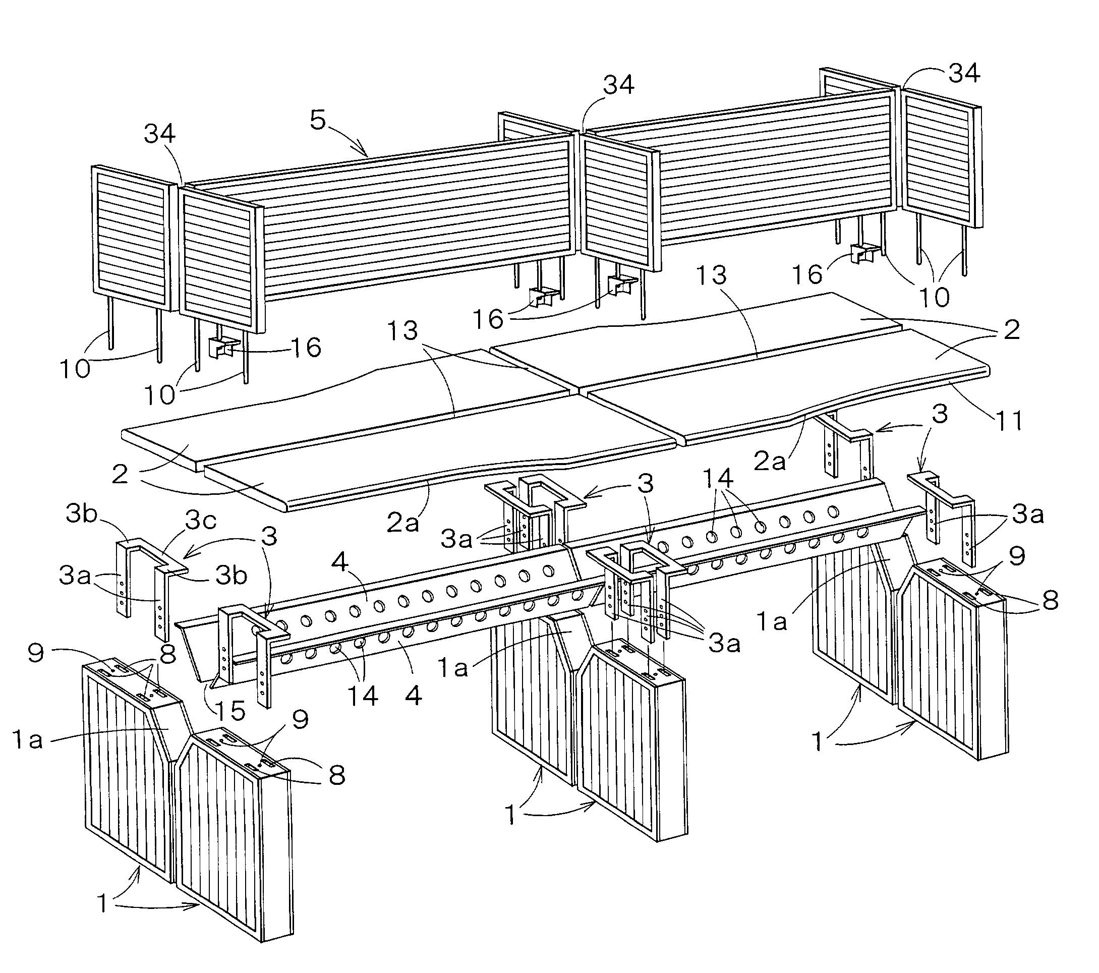
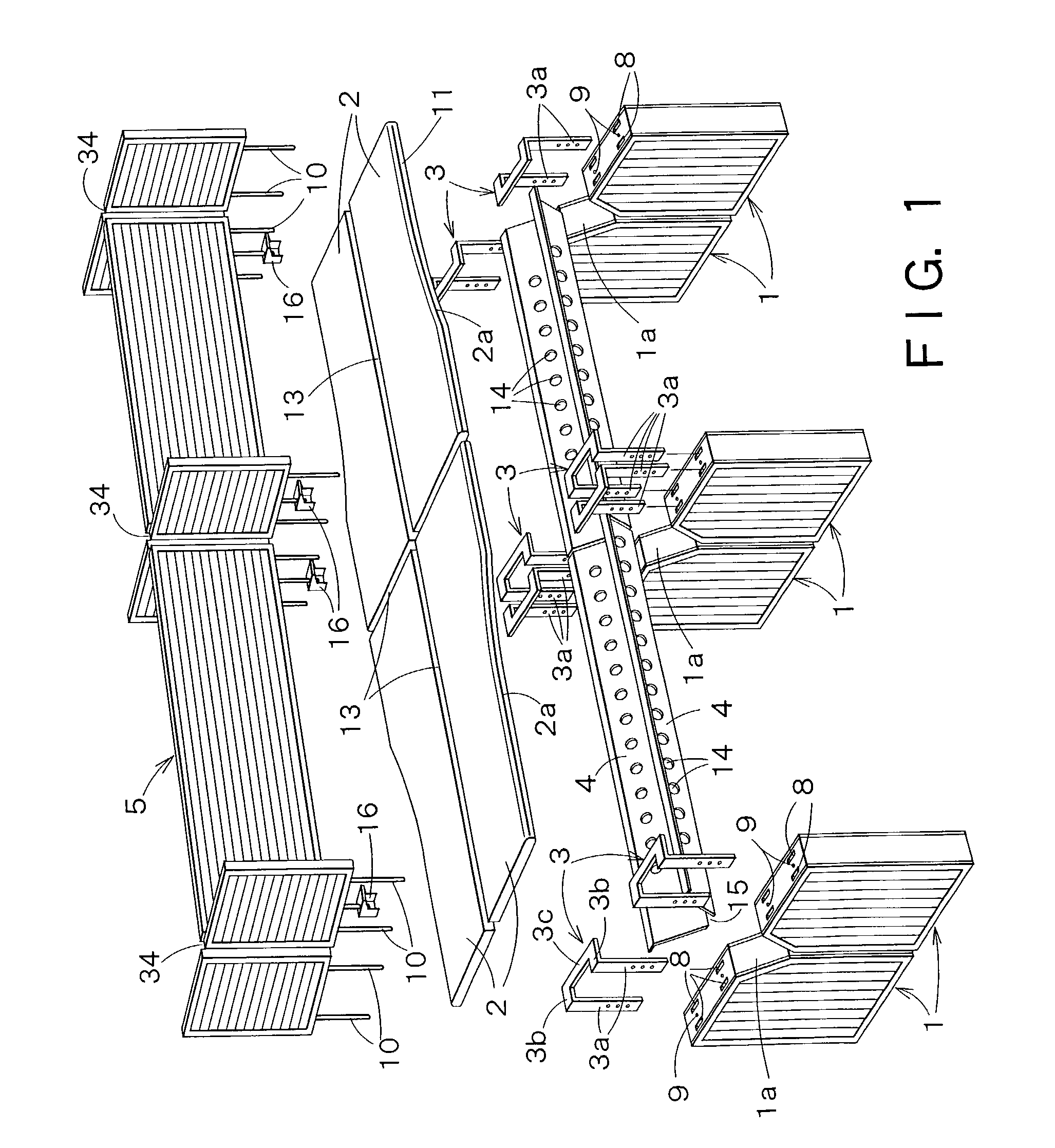
[0048]Referring to FIG. 1, an opposed-desk type desk system in a first embodiment according to the present invention comprises leg panels 1, top boards 2, top board support members 3 for fixedly supporting the top boards 2 on the leg panels 2; beams 4 connecting the leg panels 1 and forming a cable trough, and screen panels 5.
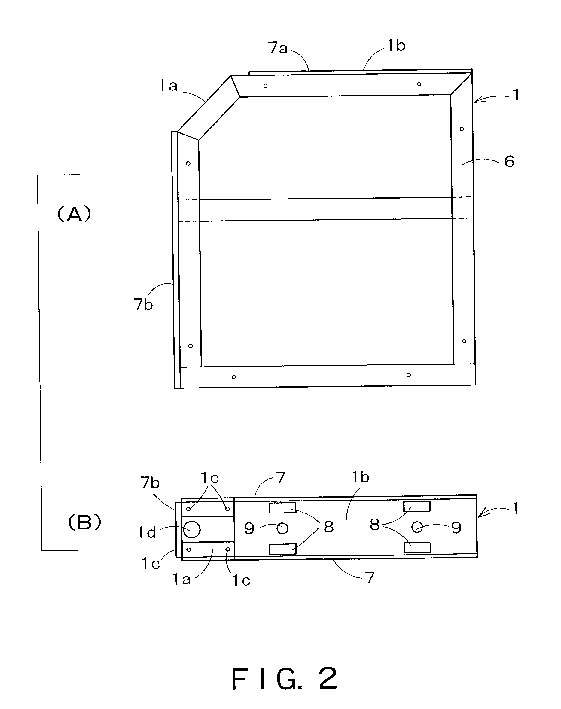
[0049]As shown in FIGS. 1 and 2(A), the leg panels 1 are paired by installing the two leg panels 1 laterally contiguously in a symmetrical shape.
[0050]Each leg panel 1 has a predetermined thickness and is formed in a vertically elongate rectangular shape. Opposed upper corners of the pair of leg panels 1 are truncated to form cut corners 1A defined by bevel surfaces 1a inclined at about 45° to a horizontal plane. When the pair of leg panels 1 are installed as shown in FIG. 1, the bevel surfaces 1a form a V-shaped groove. An upper corner of each leg panel 1 may be cut, instead of being truncated as shown in FIG. 3(A), to form a cut corner 1A defined by an L-shap...
second embodiment
[0064]FIGS. 12 to 15 show a single-row working desk system in a second embodiment according to the present invention. The desk system comprises two leg panels 1, a single beam 4, a single top board 2, a single screen panel 5, screen panel holding members 16 for holding the screen panel 5 on the beam 4, and height adjusting devices 17 for adjusting the height of the screen panel 5. The height adjusting device 17 can be used for adjusting the height of the screen panels 5 of the opposed-desk type desk system shown in FIG. 1.
[0065]The opposite ends of the beam 4 are fastened to the bevel surfaces 1a of the two leg panels 1 with screws, and the screen panel holding members 16 are attached to lower parts near the lower edge of the beam 4.
[0066]Referring to FIG. 13, the screen panel holding member 16 is a polygonal block having an oblique surface 16a inclined at an angle equal to the inclination of the beam 4. The screen panel holding member 16 is provided with a retaining projection 18 p...
PUM
 Abstract
Description
Claims
Application Information
 - R&D
- Intellectual Property
- Life Sciences
- Materials
- Tech Scout
- Unparalleled Data Quality
- Higher Quality Content
- 60% Fewer Hallucinations
Browse by: Latest US Patents, China's latest patents, Technical Efficacy Thesaurus, Application Domain, Technology Topic, Popular Technical Reports.
© 2025 PatSnap. All rights reserved.Legal|Privacy policy|Modern Slavery Act Transparency Statement|Sitemap|About US| Contact US: help@patsnap.com


