
Remote control apparatus and system in which identification or control information is obtained from a device to be controlled

a remote control and information technology, applied in the field of information processing apparatus, can solve the problems of deteriorating usability, repeated setup, and high probability of operators wasting time and money, and achieve the effect of easy control of a variety of devices

Inactive Publication Date: 2005-09-20
CANON KK
View PDF14 Cites 57 Cited by
  • Summary
  • Abstract
  • Description
  • Claims
  • Application Information

AI Technical Summary

Benefits of technology

[0009]To resolve the above shortcomings, it is one objective of the present invention to provide an information processing apparatus that can easily control a variety of devices, and a system therefor.
[0010]It is another objective of the present invention to provide a remote control apparatus that can easily cope with a plurality of devices without a series of complicated setups being required of a user and that can control the devices from a remote location, and a system therefor.
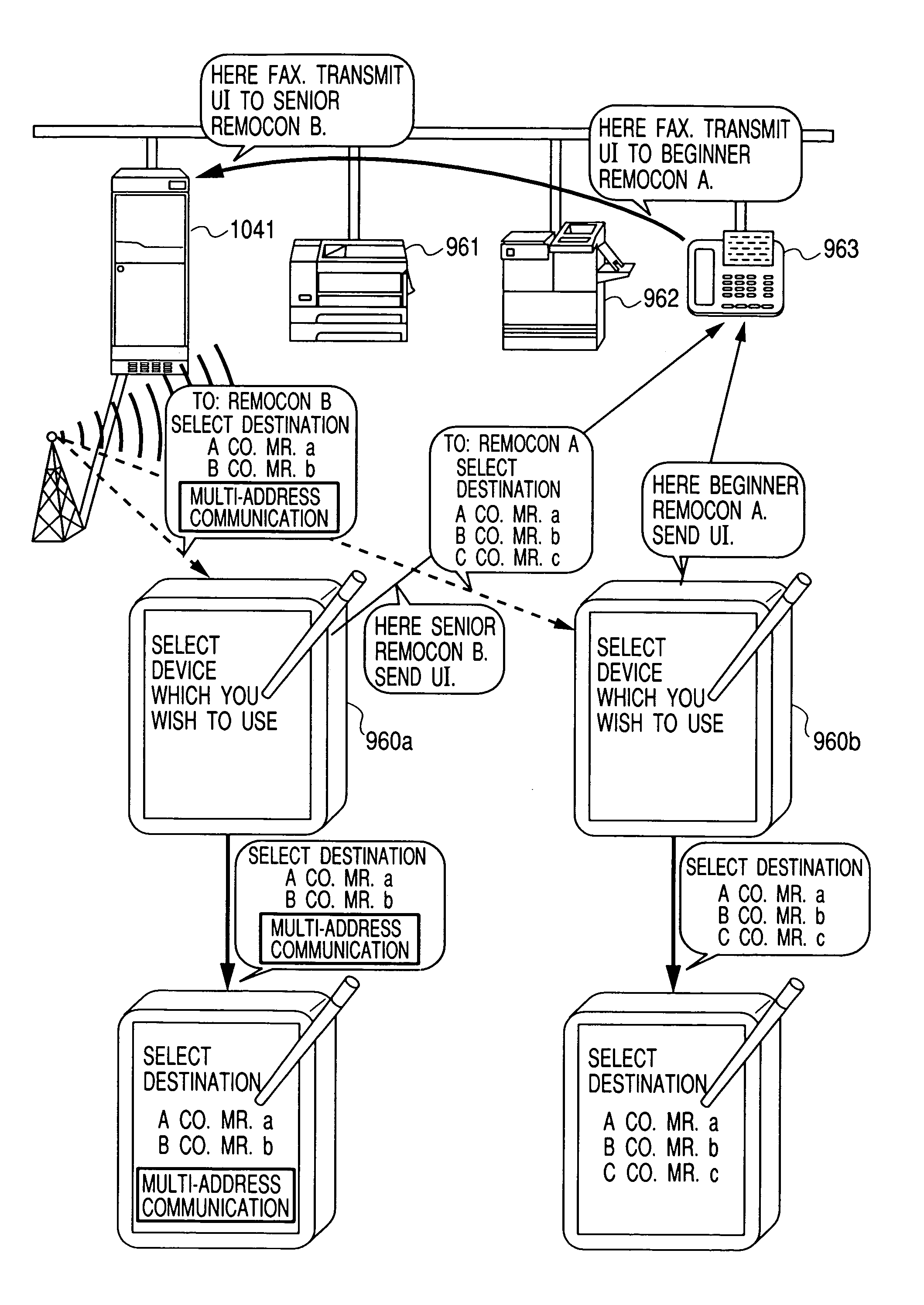
[0011]It is an additional objective of the present invention to provide a remote control system that can control, via a nearby device, a device in a remote location to which instructions can not be directly transmitted.

Problems solved by technology

Thus, as the number of compatible models has increased, setup operations have become so complicated that operators must accurately identify models that are to be controlled and must then refer to operation manuals to set up remote controllers, so that the likelihood is great that operators will mistake when they perform setups.
And when the models that are to be controlled are changed frequently, the setup must be repeated often and usability will be deteriorated.
The devices that are to be controlled by such remote controllers are limited to those that are located that they are inside the effective range of the control signals emitted by the remote controllers.

Method used


Image

  • Remote control apparatus and system in which identification or control information is obtained from a device to be controlled
  • Remote control apparatus and system in which identification or control information is obtained from a device to be controlled
  • Remote control apparatus and system in which identification or control information is obtained from a device to be controlled

Examples


tenth embodiment

[0333]In the processing for the ninth embodiment, wherein, at steps S158 and S159, a locally owned apparatus determines to perform a job itself, and performs the job, before another instructed job is performed, the possibility of the occurrence of a problem is analyzed in detail, as in the procedures in FIG. 17. When it is ascertained, in consonance with environmental conditions or the status of the job performance, that performing the job is not advisable, a notice concerning the problem may be issued, or the request for the performance of the job may be rejected.

[0334]When, for example, an instruction for printing a secret document is issued and a user is not identified as an authorized user, the instruction is rejected.

[0335]FIG. 18 is a flowchart showing the detailed procedures for the performance of a job.

[0336]At step S180 a check is performed to determine whether or not a problem exists concerning the performance of the instructed job. At step S181 no problem affecting the pe...

eleventh embodiment

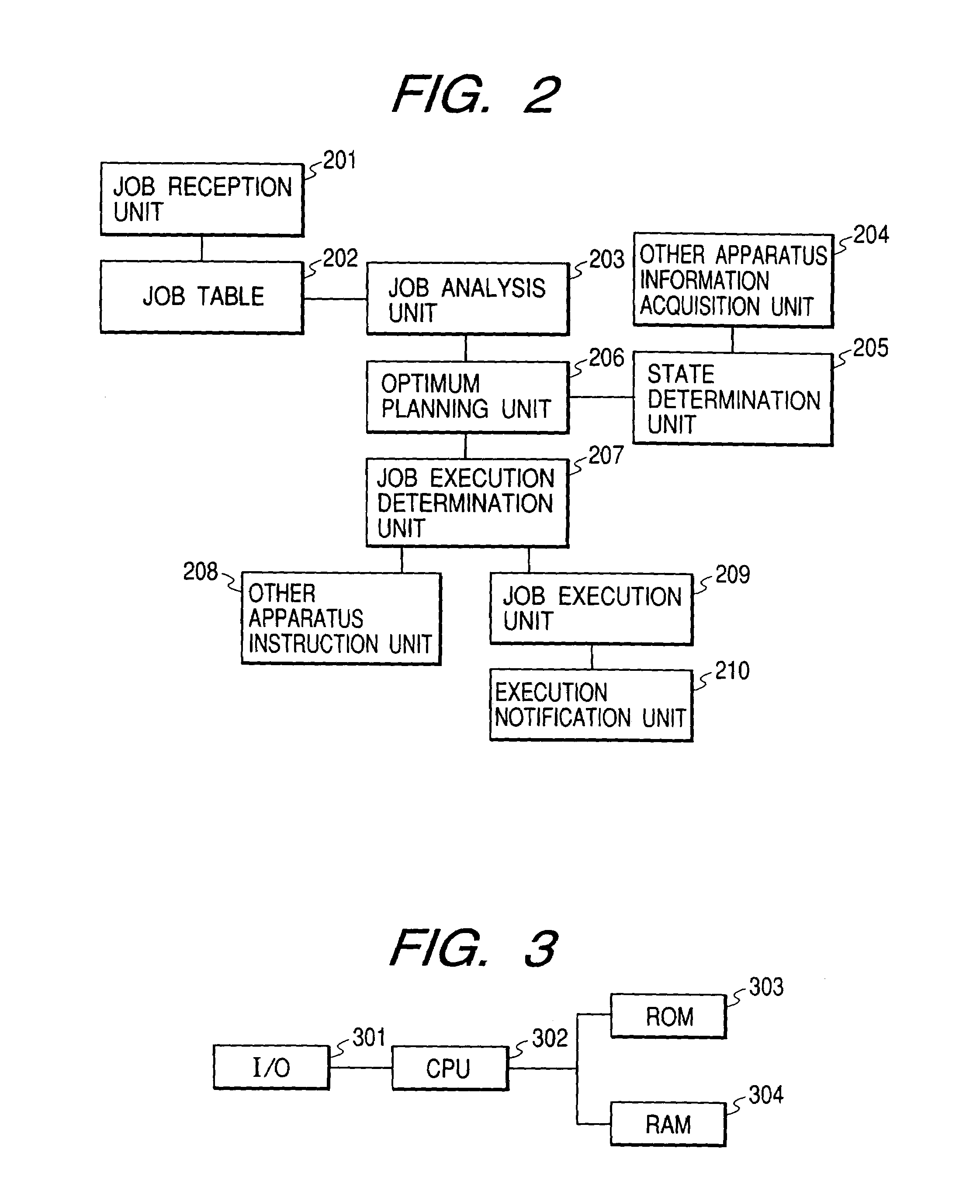
[0342]The processing for an eleventh embodiment will now be described while referring to FIG. 4. At step S109 the job table is initialized. Then, at step S110 a check is performed to determine whether there is input from a user or from an apparatus that can be detected by the system. At step S111 an input analysis job is entered in the job table to analyze the contents input at step S110. At step S112 a check is performed to determine whether there is a job to be performed. If there is such a job, it can be acquired at step S113. At step S114, the object comprising the background for the performance of the job is understood.

[0343]At step S115 a possible process is planned by using the contents that are input, the status of a device that can be detected by the system, and the knowledge that the system has currently acquired. At step S116 a new job is added if necessary. At steps S117 to S119 the process as planned at step S115 is performed in consonance with the contents. The process...

twelfth embodiment

[0371]An explanation will now be given for the processing performed in a case where, as in the eleventh embodiment, a color printer is busy when is to be printed.

[0372]First, when “Print ” is input, it is entered in the job table, and its object is understood to be a request that printing be performed. Assume as the condition / situation that the colored portion is included in a document and a color printer is busy. A plan is devised to query a user concerning whether the job can wait until the color printer is not busy, or whether the data can be printed in monochrome. The query, “The color printer is busy. Wait, or print in monochrome?” is presented to a user. When the user selects “Wait” the process is placed on standby until the color printer is no longer busy.


PUM


Abstract

A remote controller for exchanging information using infrared rays requests the direct transmission of a user interface (UI) to a device to be controlled, such as a printer or a facsimile machine, or the indirect transmission through another device that is connected to the device that is to be controlled. When the UI is returned upon receipt of the request, the menu of functions that the device that is to be controlled can execute using the UI is displayed on the screen of the remote controller, and a command to select function that is selected from the menu is transmitted to the device that is to be controlled.

Description

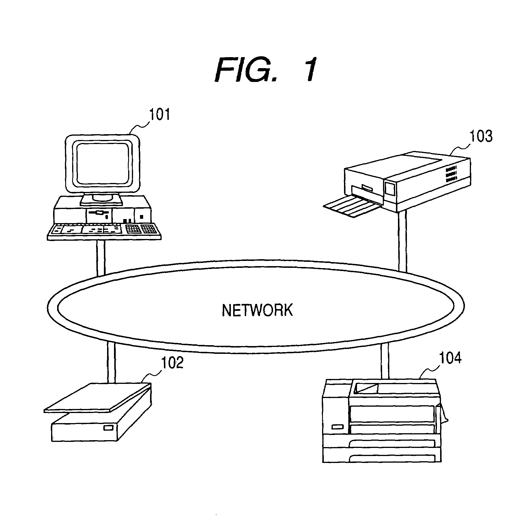
BACKGROUND OF THE INVENTION[0001]1. Field of the Invention[0002]The present invention relates to an information processing apparatus that can operate various devices indirectly by directly operating a remote controller, or another device connected with the remote controller, and a system therefor.[0003]2. Related Background Art[0004]A remote controller for exercising operational control of an apparatus from a remote location is employed primarily for home electric appliances, such as video recorders and air conditioners.[0005]In addition, remote controllers that are used for televisions and video recorders, and remote controllers that are compatible with a plurality of television models have appeared.[0006]In order to operate a specific model by using a conventional remote controller that is compatible with a plurality of models, an operator must change the setup in the remote controller.[0007]Thus, as the number of compatible models has increased, setup operations have become so co...

Claims


Application Information

Patent Timeline
IPC IPC(8): G06F3/00H04B1/20
CPCG06F3/00H04B1/202
Inventor JEYACHANDRAN, SURESHIBARAKI, SHOUICHITAKAYAMA, MASAYUKISUDA, ARUNA ROHRAWAKAI, MASANORIMIKAME, SHUICHIFUJII, KENICHITAKAHASHI, SATOMI
Owner CANON KK
Learn More