Apparatus for uniform flow distribution of gas in processing equipment

a technology of processing equipment and apparatus, which is applied in the field of apparatus for uniform flow distribution of gas in processing equipment, and the system for treating a work piece, can solve the problems of insufficient gas use in order to maintain the entire area of the furnace at the same temperature, increase furnace operating expenses, and insufficient temperature of the entire work piece, etc., to achieve the effect of simple and economical manufacture and assembly

Active Publication Date: 2006-05-02
SECOWARWICK
View PDF12 Cites 1 Cited by
  • Summary
  • Abstract
  • Description
  • Claims
  • Application Information

AI Technical Summary

Benefits of technology

[0009]Accordingly, the aspects of the invention provide a system that produces uniform re-circulating gas flow in processing equipment that is relatively simple and economical to manufacture and assemble.
[0010]Aspects of the invention separately provide a system that produces uniform re-circulating gas flow in processing equipment that is independent of the work piece size and a system and method for material conveyance that can operate at high temperatures.
[0012]Aspects of the invention separately provide a system that produce uniform re-circulating gas flow in processing equipment that can provide high velocity gas flow for enhanced and improved heat transfer capability.

Problems solved by technology

However, using gas at a uniform temperature in order to maintain all of the areas of the furnace at the same temperature alone is not sufficient.
One problem that can exist is that the temperature of the entire work piece, from the exterior of the work piece to the interior of the work piece, may not be uniformly heated or cooled.
If the furnace is thus operated for longer periods of time, furnace operating expenses also increase.
In particular, work piece to work piece uniformity will not be uniform if the flow rate of heating and cooling gas or the rate of delivery of the gas is not uniform.
Although the movable baffles are preferred over the fixed baffles, it is difficult to adapt any one method of moving the baffles to wide variations of the types of work pieces that are processed.
Because it is difficult to adapt any one method of moving the baffles, the furnaces are typically set to one specific type of workpiece.

Method used


Image

  • Apparatus for uniform flow distribution of gas in processing equipment
  • Apparatus for uniform flow distribution of gas in processing equipment
  • Apparatus for uniform flow distribution of gas in processing equipment

Examples


Embodiment Construction

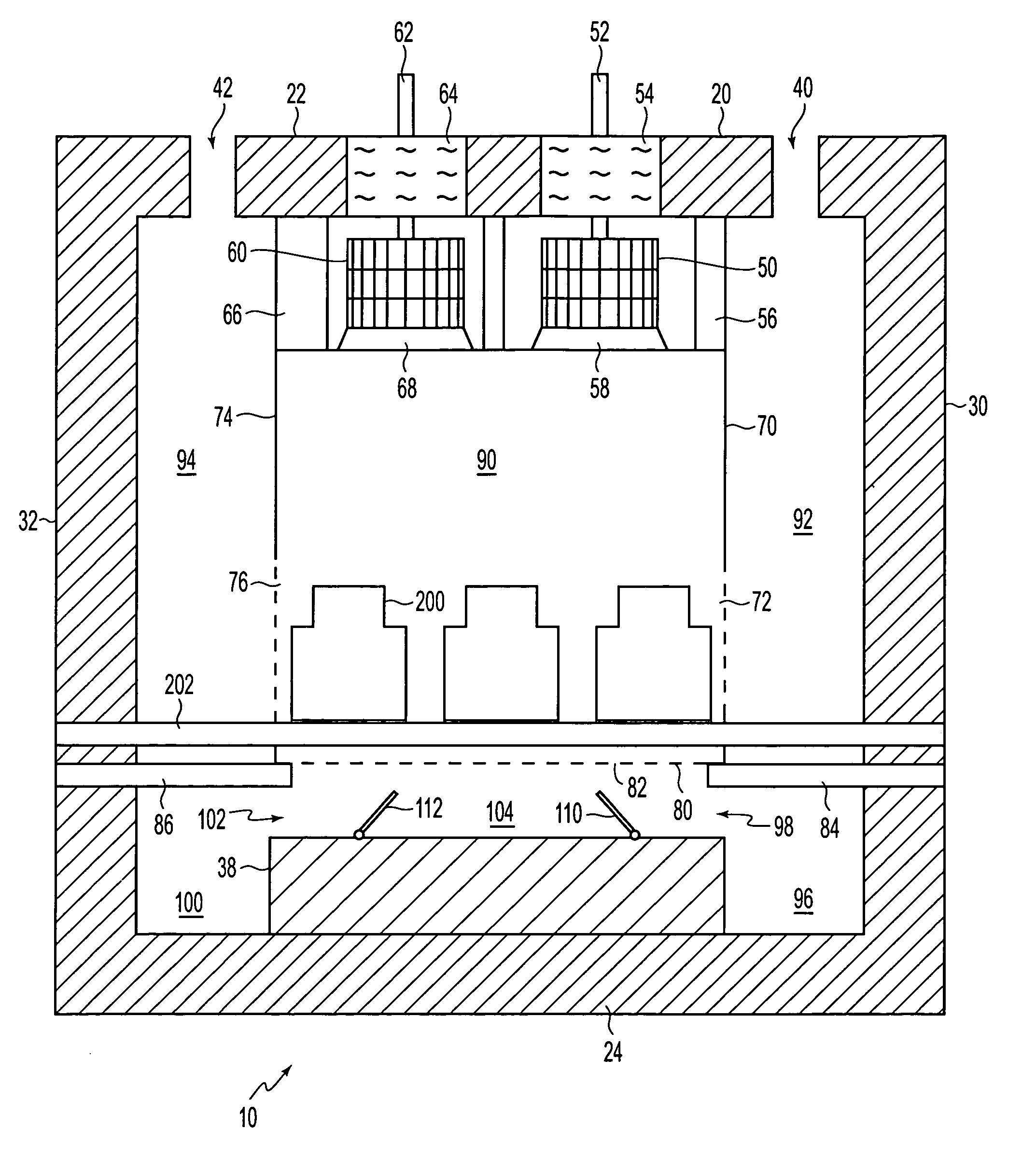
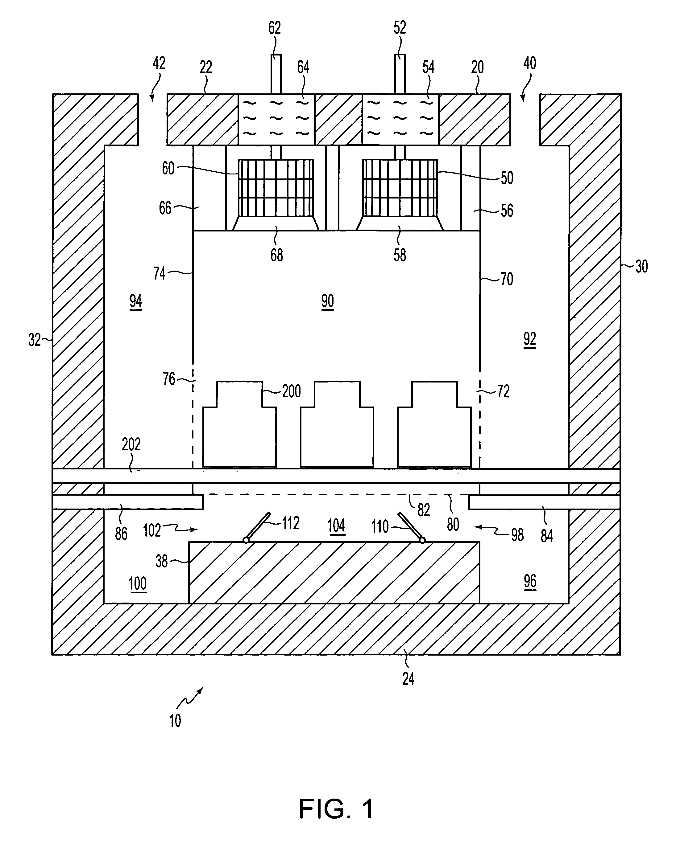
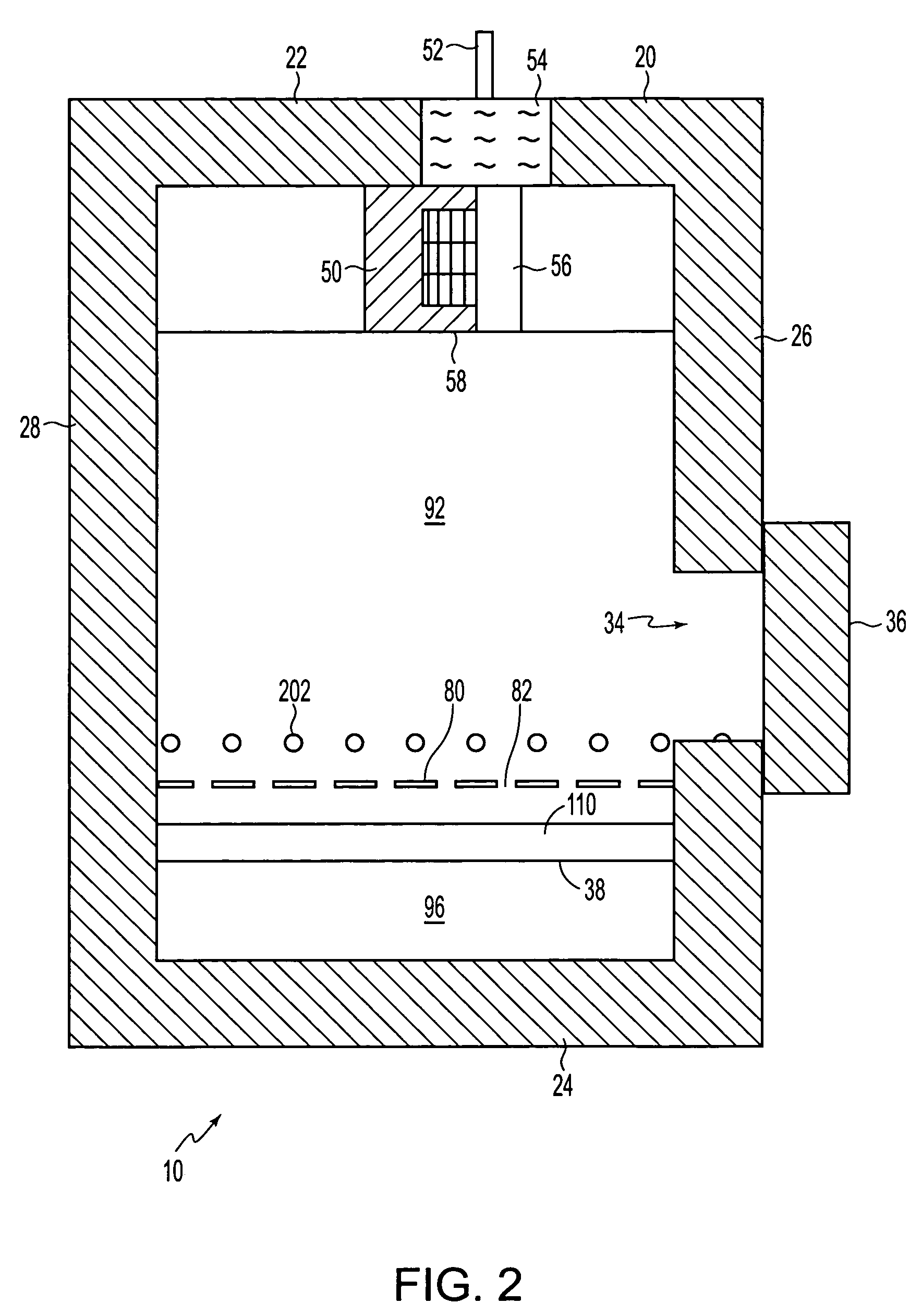
[0024]Referring now in detail to the drawings, there is illustrated in FIGS. 1–3, a furnace as an example of processing equipment. For simplicity and clarification, the operating principles and design factors of the invention are explained with reference to an embodiment of a furnace according to the invention, as shown in FIGS. 1–3. The basic explanation of the operation of the furnace shown in FIGS. 1–3 is applicable for the understanding and design of any processing equipment that incorporates the uniform flow systems and methods according to the invention.

[0025]FIGS. 1–3 show a batch type furnace 10, preferably of metal construction, with a layer of insulating refractory material on the interior to form an insulated enclosure 20. The enclosure 20 has a generally horizontal top wall 22 and bottom wall 24, a generally vertical front wall 26 and rear wall 28, and generally vertical side walls 30, 32. The front wall 26 is formed with a large entrance opening 34 which is adapted to b...


PUM


Abstract

A uniform flow control system for processing equipment with a plurality of work pieces located within the processing equipment, including a gas circulating device that circulates gas, a work chamber that can accommodate the plurality of work pieces and an expansion chamber that is located outside the work chamber and that guides gas to the work chamber. The expansion chamber includes a first chamber that extends along a first surface of the work chamber, a second chamber that extends along a second surface of the work chamber to a side of the first chamber, and a third chamber that extends from an end of the first chamber that is opposite the gas circulating device and below an end of the second chamber that is opposite the gas circulating device.

Description

BACKGROUND OF THE INVENTION[0001]1. Field of Invention[0002]The invention relates generally to processing equipment. More particularly, the invention relates to a system for treating a work piece with a uniform flow distribution.[0003]2. Description of Related Art[0004]There exists furnaces, as an example of processing equipment, that are used to treat various work pieces. Typically, a work piece is placed in a furnace and the temperature of the work piece is raised or lowered to a predetermined temperature. The treatment can be used for a wide variety of processes that include, for example, low temperature food processing to high temperature metallurgical processing. The temperature of the work piece is maintained at the predetermined temperature for a selected period of time until the work piece is sufficiently treated.[0005]When the temperature of the work piece is raised or lowered to the predetermined temperature, gas in many cases is typically distributed and re-circulated thr...

Claims


Application Information

Patent Timeline
Patent Type & Authority Patents(United States)
IPC IPC(8): F24C15/32
CPCF27B5/04F27B17/0083F27B17/0016
Inventor SHEFSIEK, PAUL
Owner SECOWARWICK
Why Eureka
Try Eureka