
Apparatus and method for limiting excessive engine speeds in a light-duty combustion engine

Active Publication Date: 2007-06-07
WALBRO LLC
View PDF7 Cites 0 Cited by
  • Summary
  • Abstract
  • Description
  • Claims
  • Application Information

AI Technical Summary

Benefits of technology

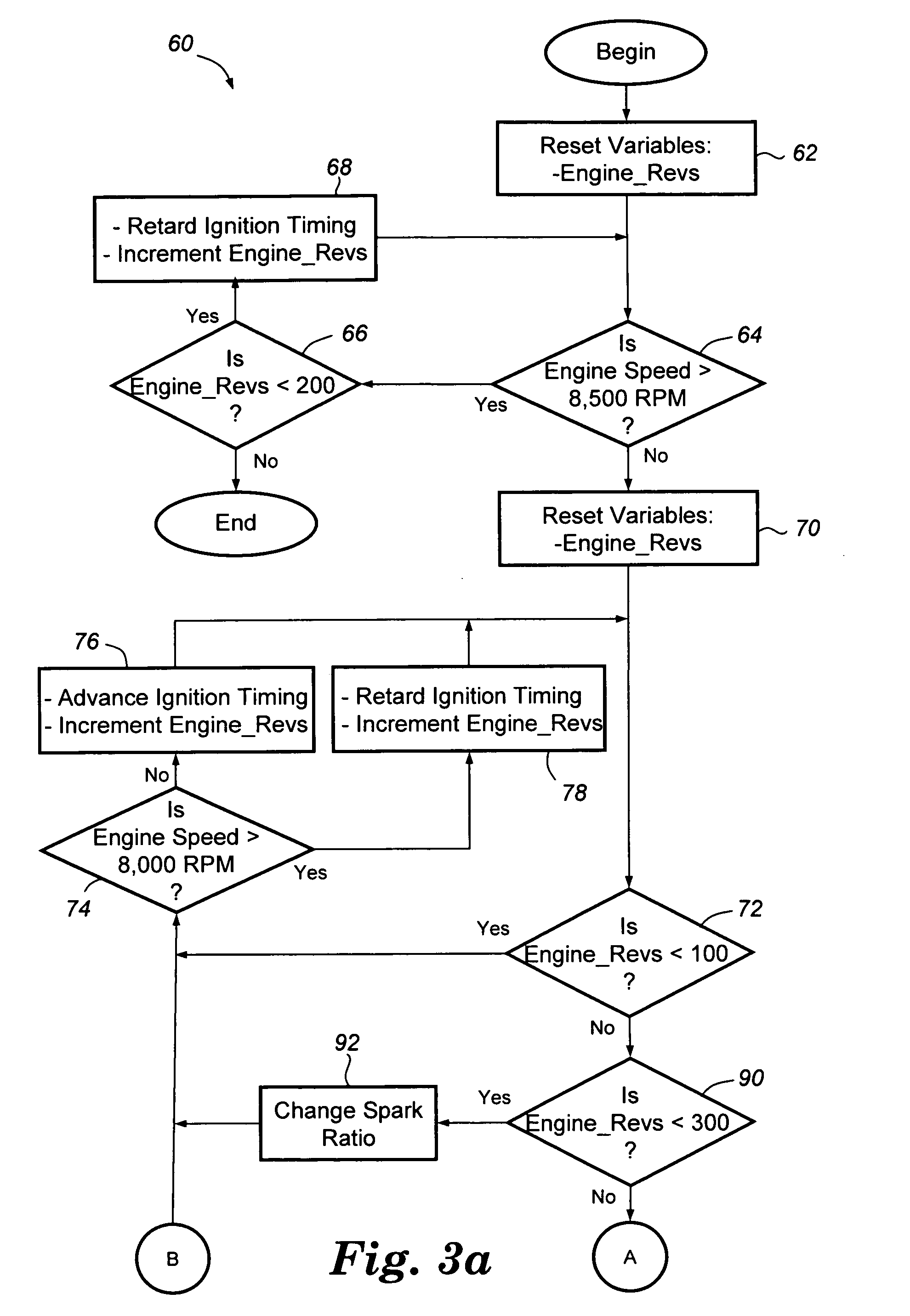
[0006] According to another embodiment, there is provided an ignition control method for use with a light-duty combustion engine. This method includes the steps of: (a) determining an engine speed, (b) comparing the engine speed with an activation speed, and (c) initiating a controlled slow down method when the engine speed exceeds the activation speed for a predetermined number of engine revolutions. The controlled slow down method manipulates ignition timing and a spark ratio in order to slow down the speed of the engine in a controlled manner.

Problems solved by technology

Most light-duty combustion engines have some type of engine speed limiting device that prevents the engine from experiencing excessive speeds that could otherwise cause unwanted damage or catastrophic failure.
Though this approach is usually effective, under certain operating conditions the engine may experience a situation where an unintentional ignition occurs even though the ignition system has not provided any spark.

Method used


Image

  • Apparatus and method for limiting excessive engine speeds in a light-duty combustion engine
  • Apparatus and method for limiting excessive engine speeds in a light-duty combustion engine
  • Apparatus and method for limiting excessive engine speeds in a light-duty combustion engine

Examples


Embodiment Construction

[0012] The controlled slow down method disclosed herein limits excessive engine speed for a light-duty combustion engine so that undesirable damage to the engine, operator, or others can be avoided. Preferably, the controlled slow down method is embodied in some form of electronic instructions that are automatically executed by an ignition control circuit which is part of a larger spark ignition system. The following paragraphs describe examples of a spark ignition system and an ignition control circuit that may utilize the controlled slow down method, however, they are just illustrative examples and numerous other systems and circuits could be utilized instead.

Ignition System

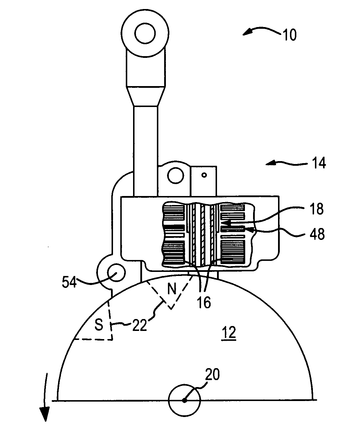
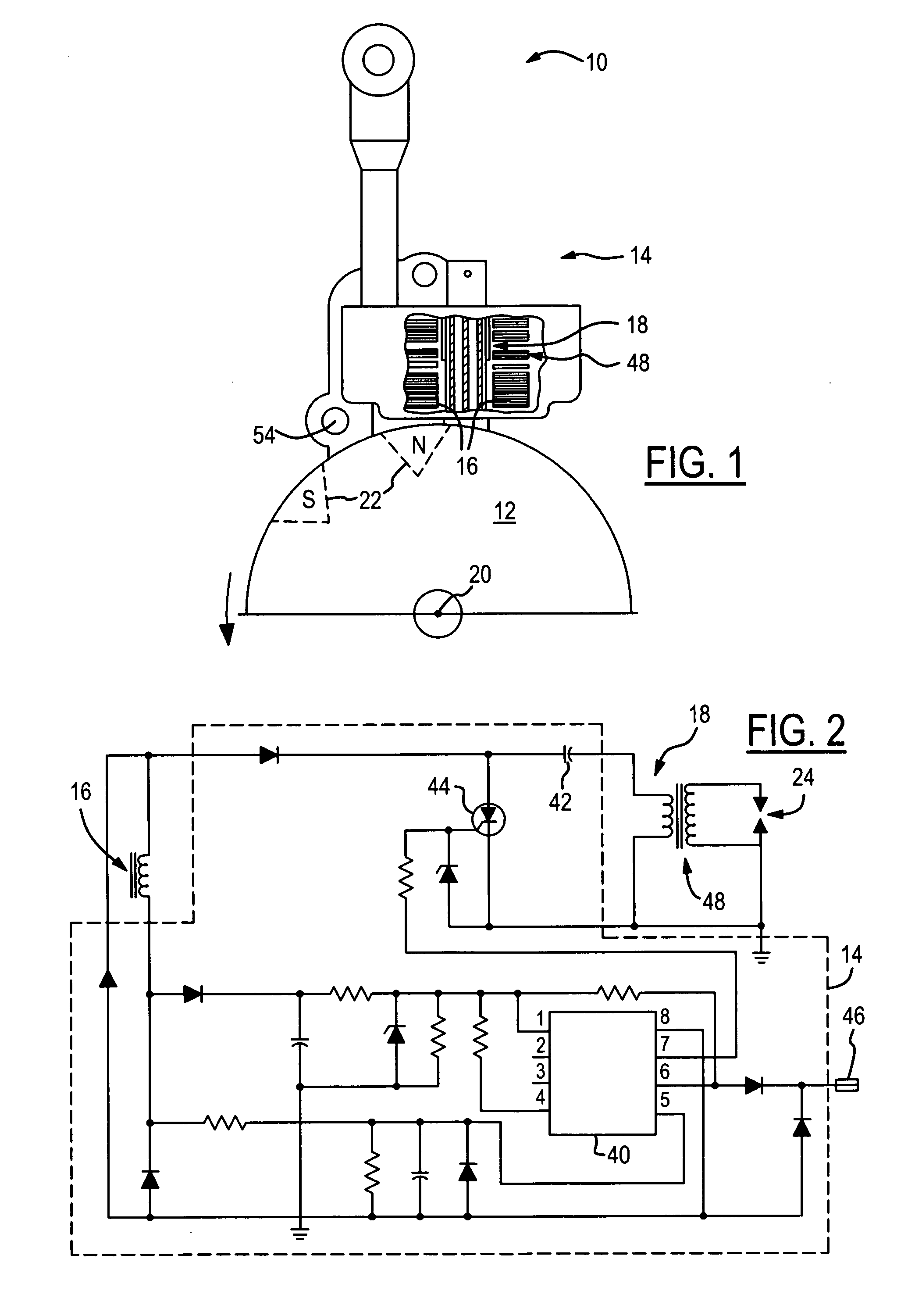
[0013] Referring to FIG. 1, there is shown an example of an ignition system 10 for a light-duty combustion engine that can utilize the controlled slow down method disclosed herein. Ignition system 10 is preferably a capacitive discharge-type ignition system that interacts with a flywheel 12 and generally inc...


PUM


Abstract

A controlled slow down apparatus and method for use in the event that a light-duty combustion engine has entered a state of excessive speeds or auto-ignition. The controlled slow down method is preferably initiated when the engine speed exceeds an activation speed for a predetermined number of engine revolutions. Once initiated, the controlled slow down method uses a combination of ignition timing and spark ratio manipulations in order to disrupt the auto-ignition conditions and slow down the engine in a controlled manner. Preferably, the controlled slow down method is only one part of an overall ignition control method, and can be incorporated within or utilized by one of a number of different ignition timing methods known in the art.

Description

FIELD OF THE INVENTION [0001] The present invention generally relates to ignition systems for light-duty combustion engines, and more particularly, to ignition control circuits and methods for limiting excessive engine speeds. BACKGROUND OF THE INVENTION [0002] The term ‘light-duty combustion engine’ used herein broadly includes all types of non-automotive combustion engines including, but not limited to, two-and four-stroke engines used with hand-held power tools, lawn and garden equipment, lawnmowers, weed trimmers, edgers, chain saws, snowblowers, personal watercraft, boats, snowmobiles, motorcycles, all-terrain-vehicles, etc. Most light-duty combustion engines have some type of engine speed limiting device that prevents the engine from experiencing excessive speeds that could otherwise cause unwanted damage or catastrophic failure. [0003] For instance, it is known to provide a light-duty combustion engine with a device that restricts the engine speed by simply stopping the combu...

Claims


Application Information

Patent Timeline
IPC IPC(8): F02P11/00
CPCF02D2400/06F02P5/1502F02P9/005Y02T10/46Y02T10/40
Inventor ANDERSSON, MARTIN N.PATTULLO, GEORGE M.
Owner WALBRO LLC
Learn More