
Motor stop control device utilizable for reel-type gaming machine

a technology of stepping motor and control device, which is applied in the direction of motor/generator/converter stopper, dynamo-electric converter control, instruments, etc., can solve the problems of high torque, high production cost of reel unit including stepping motor, and high cost of stepping motor, so as to reduce motor cost and reduce motor braking. the effect of less manday

Active Publication Date: 2006-05-02
UNIVERSAL ENTERTAINMENT CORP
View PDF16 Cites 11 Cited by
  • Summary
  • Abstract
  • Description
  • Claims
  • Application Information

AI Technical Summary

Benefits of technology

[0009]The present invention has done taking the above situation into consideration and the object of the present invention is to provide a motor stop control device through which the reel unit can be assembled with less manday while reducing a motor cost and the reel can be precisely stopped without losing smoothness in motor braking.
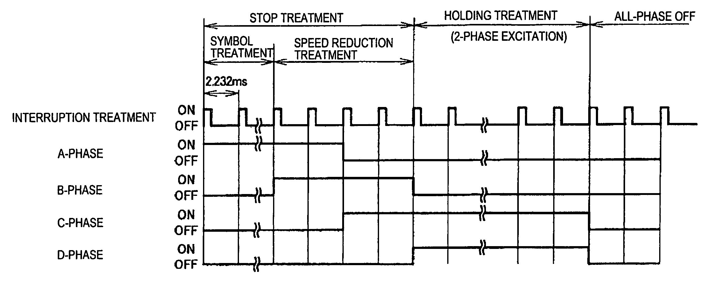
[0014]According to the motor stop control device of the present invention, the speed reduction mechanism transmits rotation of the motor to the rotation shaft of the reel with a predetermined speed reduction ratio, therefore it can be adopted the motor (for example, PM type motor) which has small rotation torque and is very inexpensive. And the motor stop controller conducts the speed reduction treatment to reduce rotation speed of the motor, thereafter conducts the excitation treatment by 2-phase excitation against the motor. Therefore, the motor stop controller can precisely stop the reel at an exact position.
[0015]Further, since the motor stop controller executes the speed reduction treatment to reduce rotation speed of the motor, the motor stop controller can stop the reel at the exact position while retaining smoothness in braking of the motor, in comparison with a case that rotation speed of the motor is rapidly reduced. As a result, since braking control does not depend on the detent torque occurring when the reel is stopped, the above balance adjustment is not needed when the motor stop control device is produced and an assembler can assemble the reel unit with less manday.
[0021]According to the motor stop control device of the present invention, the speed reduction mechanism transmits rotation of the motor to the rotation shaft of the reel with a predetermined speed reduction ratio, therefore it can be adopted the motor which has small rotation torque and is very inexpensive. And the motor stop controller conducts the speed reduction treatment to reduce rotation speed of the motor, thereafter conducts the excitation treatment by 2-phase excitation against the motor. Therefore, the motor stop controller can precisely stop the reel at an exact position.
[0022]Further, since the vibration restraining member has braking function to brake rotation of the reel and declines vibration occurring when rotation of the reel is stopped, the vibration restraining member can stop the reel at the exact position while retaining smoothness in braking of the motor. As a result, the above balance adjustment is not needed when the motor stop control device is produced and an assembler can assemble the reel unit with less manday.
[0023]As mentioned above, according to the present invention, cost of the motor can be reduced and the reel unit can be produced with less manday, further the reel can be precisely stopped at the exact position while retaining smoothness in braking of the motor.

Problems solved by technology

However, in the above direct drive manner, since it is not provided a mechanical speed reduction device the stepping motor has to produce rotation torque corresponding to inertia of the reel.
Therefore, it is adopted an expensive stepping motor (for example, hybrid-type stepping motor), which can produce high torque.
Thus, there is a problem that production cost of the reel unit including the stepping motor cannot be remarkably reduced.
However, there is imbalance in the detent torque every reel and is also imbalance in the above inertia every reel.
Therefore, stop of symbol on the reel becomes unstable, as a result, the symbol described on the surface of the reel cannot be precisely stopped.
In this case, there is a problem that manday increases when the assembler assembles the reel unit.

Method used


Image

  • Motor stop control device utilizable for reel-type gaming machine
  • Motor stop control device utilizable for reel-type gaming machine
  • Motor stop control device utilizable for reel-type gaming machine

Examples


first modification

[0148](First Modification)

[0149]The present invention is not limited to the above mentioned embodiment, and modifications can be added as follows. In the first modification, an oil damper is utilized instead of the vibration restraining member 75. FIGS. 17A and 17B are perspective views of the oil damper 90 according to the first modification.

[0150]The oil damper 90 has a rotation part 91 and a base part 92, as shown in FIGS. 17A and 17B. In the base part 92, oil with predetermined viscosity is filled. Since oil is filled in the base part 92, rotation of the rotation part 91 is damped.

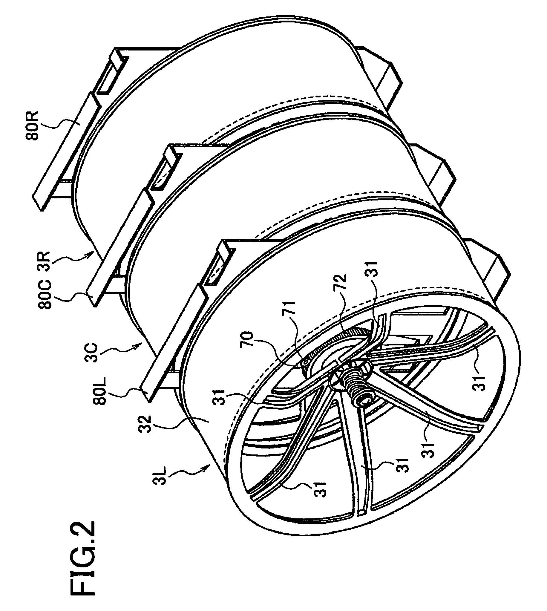
[0151]FIG. 18 is an explanatory view showing a positional relation of the oil damper in the first modification. In the oil damper 90, as shown in FIG. 18, gear teeth 91A formed in the rotation part 91 is arranged within the reel 3 so as to mesh with the input gear 72.

[0152]According to the above first modification, rotation force of the rotation part 91 is damped by oil filled in the base part 92 (damp...

second modification

[0153](Second Modification)

[0154]The present invention is not limited to the above mentioned embodiment, and modifications can be added as follows. In the second modification, a felt 751, a high frictional member such rubber and the like or a wave washer 752 is utilized instead of the vibration restraining member 75.

[0155]FIG. 19A is a plan view of the felt 751. FIG. 19B is an explanatory view indicating a positional relation when the felt 751 is arranged. As shown in FIGS. 19A and 19B, the felt 751 is formed in a circular shape and a hole to insert the stopper screw 73 is formed at the center thereof. The felt 751 is fixed by the stopper screw 73 so as not to come off.

[0156]FIG. 20A is a plan view of the wave washer 752. FIG. 20B is an explanatory view indicating a positional relation when the wave washer 752 is arranged. As shown in FIGS. 20A and 20B, the wave washer 752 is formed so as to have a wave-like plane shape from the center toward the outside and a hole to insert the sto...

third modification

[0158](Third Modification)

[0159]The present invention is not limited to the above mentioned embodiment, and modifications can be added as follows. In the third modification, a rubber roller 711 and 721 are utilized instead of the output gear 71 and the input gear 72.

[0160]FIG. 21 is an explanatory view indicating a positional relation when the rubber rollers 711 and 721 are arranged. These two rubber rollers 711, 721 contact with each other and can mutually transmit rotation because of high frictional coefficient without sliding therebetween. The rubber rollers 711, 721 are arranged inside of the reel 3. Thereby, even if vibration occurs in the rotation shaft of the reel 3 when the stepping motor 70 is braked (or when backlash occurs), the rubber rollers 711, 721 is resiliently deformed, thereby vibration can be absorbed.

[0161]Here, in the third modification, instead of the output gear 71 and the input gear 72 formed into the spur gear, a flexible belt 723 formed of soft material in...


PUM


Abstract

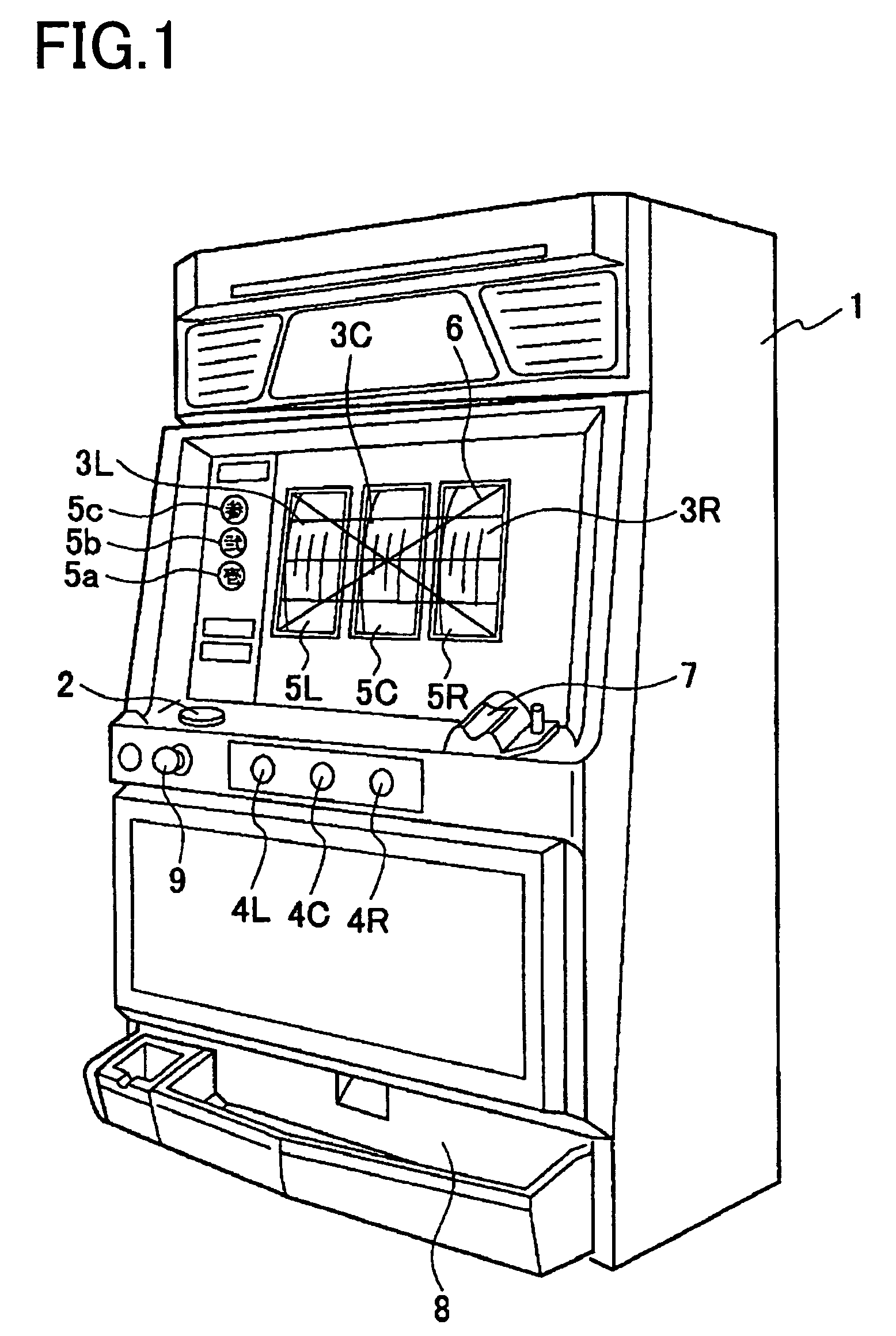
In the motor stop control device utilizable for the reel-type gaming machine 1, there are provided the stepping motor 70 having two pairs of excitation phases for rotating the reel 3 on the outer periphery of which a plurality of symbols are formed, the speed reduction mechanism 700 for transmitting rotation of the stepping motor 70 to the rotation shaft of the reel 3 with a predetermined speed reduction ratio and the main CPU 40 for conducting speed reduction treatment to reduce rotation speed of the stepping motor 70 and excitation treatment by 2-phase excitation against the stepping motor 70 when the motor stop command occurs.

Description

CROSS-REFERENCE TO THE RELATED APPLICATION(S)[0001]This application is based upon and claims a priority from the prior Japanese Patent Application No. 2003-131411 filed on May 9, 2003, the entire contents of which are incorporated herein by reference.BACKGROUND OF THE INVENTION[0002]1. Field of the Invention[0003]The present invention relates to a motor stop control device for a reel-type gaming machine, the motor stop control device having a motor with two pairs of excitation phases and stopping the motor according to an instruction command transmitted from an external.[0004]2. Description of Related Art[0005]Conventionally, in a symbol variable rotation device utilized in a reel-type gaming machine (for example, a Japanese Pachi-slot machine), a reel is directly connected to a rotor of a stepping motor (abbreviated as “direct drive manner”) as shown in Japanese Unexamined Publication No. 10-71240.[0006]However, in the above direct drive manner, since it is not provided a mechanica...

Claims


Application Information

Patent Timeline
Patent Type & Authority Patents(United States)
IPC IPC(8): H02P3/00A63F5/00G07F17/34H02P8/30
CPCG07F17/3202H02P8/30G07F17/3213
Inventor NIREKI, TAKAOOMOMO, SHINGOSUZUKI, YUUICHIROU
Owner UNIVERSAL ENTERTAINMENT CORP
Learn More