Reel unit

a reel unit and reel technology, applied in the field of reel units, can solve the problems of inconvenient giving a sense of visual disorder to the player, and achieve the effect of effectively suppressing backlash and effectively preventing backlash

Inactive Publication Date: 2006-05-04
UNIVERSAL ENTERTAINMENT CORP
View PDF19 Cites 2 Cited by
  • Summary
  • Abstract
  • Description
  • Claims
  • Application Information

AI Technical Summary

Benefits of technology

[0010] In accordance with the first aspect of the invention, since the reel and the speed reduction gear are integrally rotatably fixed radially outside their centers by the engaging portion and the engaged portion, backlash which is likely to occur during the rotation of the reel can be effectively suppressed. Specifically, since the engaging portion and engaged portion are formed to constitute a baffle between the reel and the speed reduction gear at the area on which great inertial force of the reel acts (area radially outside from the center), baffling of both reel and speed reduction gear can be effectively carried out, thereby effectively preventing the backlash at the time of starting and stopping of the rotation. When the reel is stopped or started, this prevents a pl

Problems solved by technology

This gives an inconvenience of giving a sense of visual disorder to the player such as the symbols when stopped slightly deviating from

Method used


Image

  • Reel unit
  • Reel unit
  • Reel unit

Examples


Embodiment Construction

[0019] Now referring to the attached drawings, a detailed explanation will be given of an embodiment of the reel unit according to this invention.

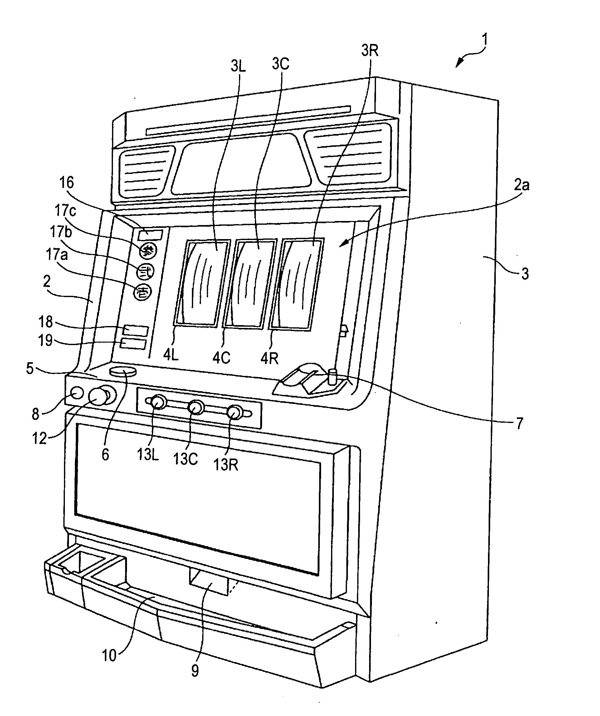
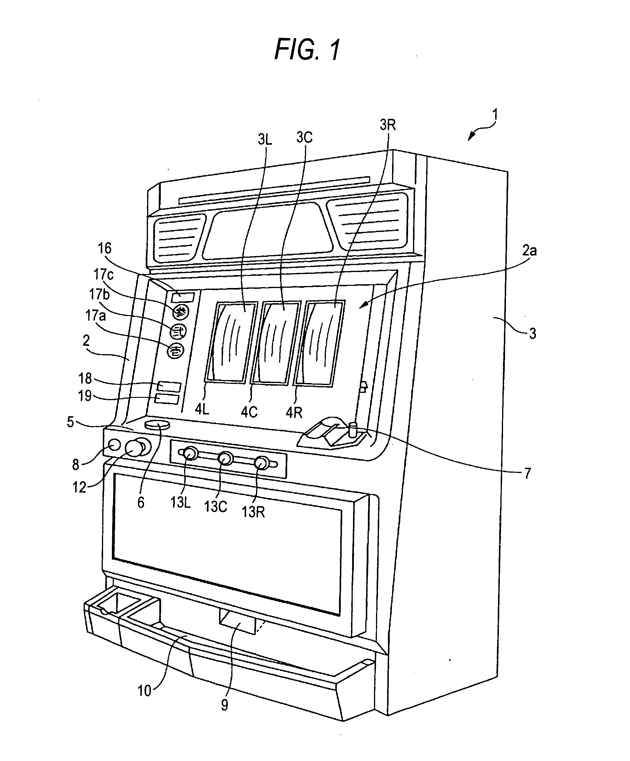
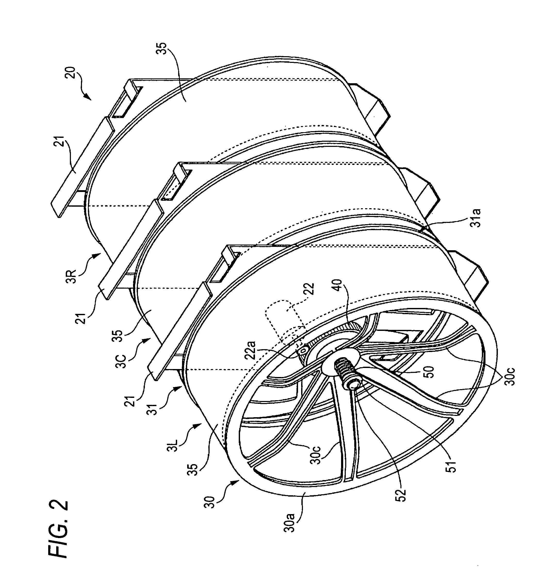
[0020]FIG. 1 is a perspective view of an embodiment of the slot machine according to this invention. FIG. 2 is a view showing the schematic structure of a reel unit built in the slot machine.

[0021] As seen from FIG. 1, a slot machine 1 has a cabinet 3 provided with a door (front door) which is openable / closable on the front face. The door 2 has a game region 2a above a nearly central position on the front face. On the game region 2, square display windows 4L, 4C and 4R are provided from which the respective reels 3L, 3C and 3R of the reel unit described later are exposed. On the outer periphery of each reel, a symbol column composed of a plurality of kinds of symbols is drawn. The symbols drawn on each reel can be visually recognized through the display window 4L, 4C, 4R. Each reel is designed to be rotatable at a constant speed (e.g. 80...


PUM


Abstract

A reel unit according to this invention includes a reel equipped with a frame body 30, on the outer periphery of which a plurality of kinds of symbols are formed; a driving motor 30 for driving the reel; and a speed reduction gear 40 for reducing an output from the driving motor, arranged at the center of the frame body so that it can be rotated integrally to the frame body. The reel unit is characterized in that an engaging portion 30 is formed radially outside its center of the frame body and an engaged portion 40 to be engaged with the engaging portion is formed at the corresponding position of the speed reduction gear 40.

Description

CROSS-REFERENCE TO THE RELATED APPLICATION(S) [0001] This application is based upon and claims a priority from prior Japanese Patent Application No. 2003-37993 filed on Nov. 10, 2003, the entire contents of which are incorporated herein by reference. This application is related to co-pending U.S. patent application Ser. No. 10 / 697,085 entitled to “Motor Stop Control Device” filed on Oct. 31, 2003 and Ser. No. 10 / 697,085 entitled to “Motor stop control device utilizable for reel-type gaming machine” filed on Apr. 29, 2004. The co-pending applications are expressly incorporated herein by reference.BACKGROUND OF THE INVENTION [0002] 1. Field of the Invention [0003] This invention relates to a reel unit built in a gaming machine such as a slot machine and having a reel on the outer periphery of which a plurality of kinds of symbols are successively formed. [0004] 2. Description of the Related Art [0005] The gaming machine such as a slot machine incorporates a reel unit as a game device ...

Claims


Application Information

Patent Timeline
IPC IPC(8): A63F1/18A63B71/00A63F5/04A63FG07F17/34
CPCG07F17/3213
Inventor EMORI, KAZUKI
Owner UNIVERSAL ENTERTAINMENT CORP
Why Eureka
Try Eureka