Insert and method for reducing fouling in a process stream

a technology of process stream and sulfide sulfide, which is applied in the direction of indirect heat exchangers, lighting and heating apparatus, transportation and packaging, etc., can solve problems such as shear motion development, and achieve the effects of reducing corrosion and fouling, reducing fouling, and reducing the difficulty of determining the upper temperature constraints

Inactive Publication Date: 2007-08-16
EXXON RES & ENG CO
View PDF63 Cites 27 Cited by
  • Summary
  • Abstract
  • Description
  • Claims
  • Application Information

AI Technical Summary

Benefits of technology

[0012] In accordance with the present invention, each heat exchanger tube may be formed from an aluminum or aluminum alloy coated carbon steel or a steel composition that is resistant to sulfidation or sulfidic corrosion and fouling. The use of aluminum or aluminum alloy coated carbon steel or a steel composition that is resistant to sulfidation and fouling significantly reduces fouling and corrosion, which produces numerous benefits including an increase in heating efficiency, a reduction in the overall amount of energy needed to heat the crude oil, an increase in refinery throughput and a significant reduction in refinery downtime.
[0025] It is another aspect of the present invention to combine corrosion resistance with a desired surface smoothness, which has synergistic impact on fouling mitigation. A smooth surface alone will reduce fouling temporarily, but with time and corrosion, the smoothness is lost and so is the initial benefit. Similarly, a rough textured, though corrosion-resistant surface is equally less effective at foulant reduction. In contrast, a smooth, corrosion-resistant surface will provide a long-lasting foulant resistant surface.

Problems solved by technology

To further reduce and / or limit fouling, the heat transfer component may be subject to a vibrational force, which results in the development of a shear motion in the liquid flowing within the heat exchanger.

Method used


Image

  • Insert and method for reducing fouling in a process stream
  • Insert and method for reducing fouling in a process stream
  • Insert and method for reducing fouling in a process stream

Examples


Embodiment Construction

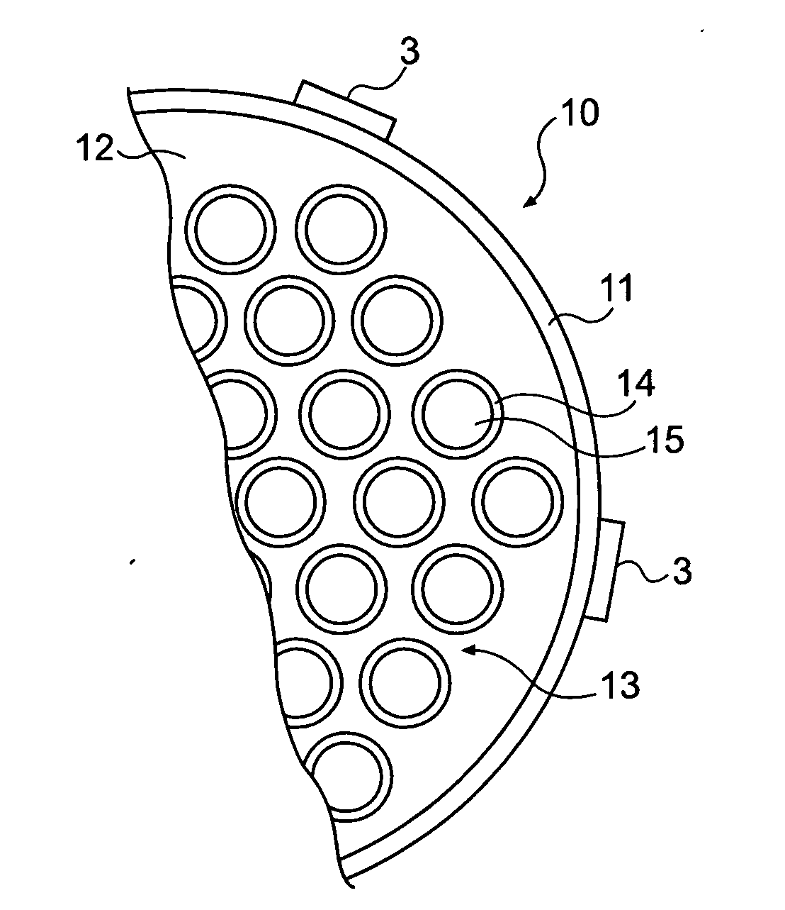
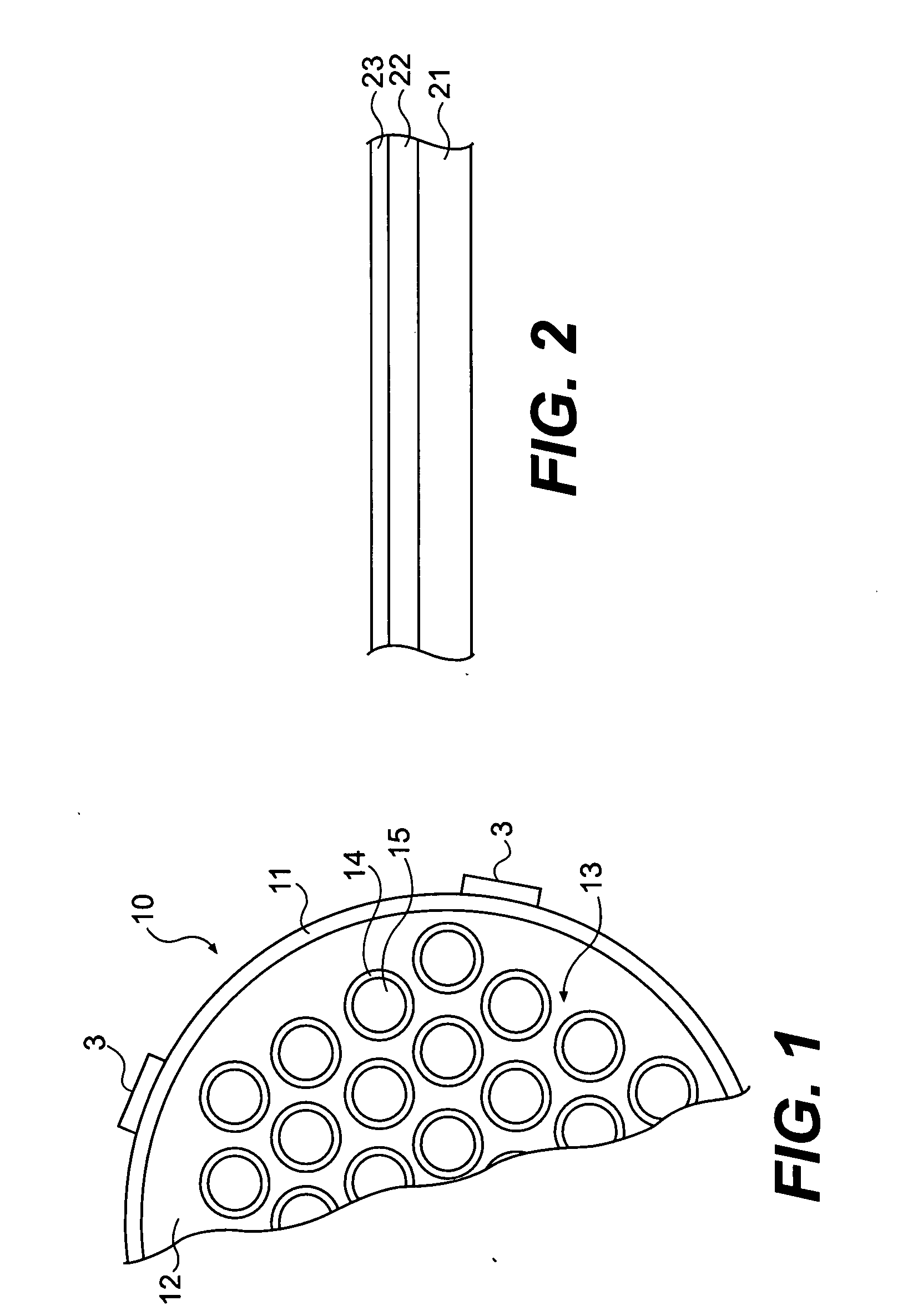
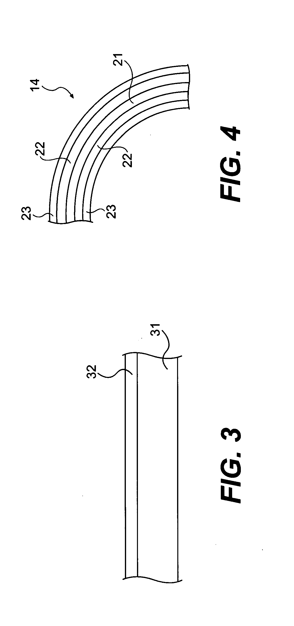
[0035] The present invention will now be described in greater detail in connection with the attached figures. FIG. 1 is a tube-in-shell heat exchanger 10, which is located upstream from a furnace (not shown) and employs the principles of the present invention. The tube-in-shell heat exchanger 10 disclosed herein illustrates one application of the present invention to reduce sulfidation or sulfidic corrosion and depositional fouling in refinery and petrochemical applications. The tube-in-shell exchanger 10 is just one heat transfer component falling under the scope of the corrosion reduction and fouling mitigation measures in accordance with the present invention. The principles of the present invention are intended to be used in other heat exchangers including but not limited to spiral heat exchangers, tube-in-tube heat exchangers and plate-and-frame heat exchangers having at least one heat transfer element. The principles of the present invention are intended to be employed in othe...


PUM

PropertyMeasurementUnit
temperaturesaaaaaaaaaa

Abstract

An insert for reducing sulfidation corrosion and depositional fouling is disclosed. The insert is formed from a corrosion and fouling resistant steel composition containing a Cr-enriched layer and having a surface roughness of less than 40 micro inches (1.1 μm).

Description

CROSS REFERENCE TO RELATED APPLICATION [0001] This application relates to and claims priority to U.S. Provisional Patent Application No. 60 / 751,985, filed Dec. 21, 2005, entitled “Corrosion Resistant Material For Reduced Fouling, A Heat Exchanger Having Reduced Fouling And A Method For Reducing Heat Exchanger Fouling in a Refinery”, U.S. Provisional Patent Application No. 60 / 815,844, filed Jun. 23, 2006 entitled “A Method of Reducing Heat Exchanger Fouling in a Refinery” and U.S. Provisional Patent Application No. 60 / 872,493 (Attorney Docket No.: 2006EM194) filed Dec. 4, 2006 entitled “An Insert and Method For Reducing Fouling in A Process Stream,” the disclosures of which are hereby incorporated specifically herein by reference.FIELD OF THE INVENTION [0002] This invention relates to the reduction of sulfidation or sulfidic corrosion and the reduction of depositional fouling in general and in particular the reduction of sulifidation / sulfidic corrosion and the reduction of deposition...

Claims


Application Information

Patent Timeline
Patent Type & Authority Applications(United States)
IPC IPC(8): F28F13/18F28F9/02
CPCC10G9/203F28D7/16F28D2021/0059F28F19/00F28F19/002F28F19/02Y10T428/12549F28F21/082F28F25/08F28G7/00C10G2300/4075F28F21/083Y10T428/1259F28F19/06C22C38/00B32B15/012B32B15/011C23F15/00C22C38/18C22C38/02C22C38/22C22C38/04C22C38/60C22C38/50C22C38/44C22C38/48C22C38/38F28F13/10
Inventor GREANEY, MARK A.FEATHER, JAMES E.BRUNO, THOMASCHUN, CHANGMINHAY, CLIFFORD A.
Owner EXXON RES & ENG CO
Why Eureka
Try Eureka