Piezo-electric microactuator for dual stage actuator

Inactive Publication Date: 2006-05-02
SEAGATE TECH LLC
View PDF10 Cites 17 Cited by
  • Summary
  • Abstract
  • Description
  • Claims
  • Application Information

AI Technical Summary

Benefits of technology

[0011]The driving frame portion has piezoelectric element that in response to a control signal produces a force, orthogonal to the flexure's longitudinal axis, between the base plate portion and the load beam portion. Embodiments of the dr

Problems solved by technology

However, these means of increasing track density are limited by the precision of the actuator and voice coil motor assem

Method used


Image

  • Piezo-electric microactuator for dual stage actuator
  • Piezo-electric microactuator for dual stage actuator
  • Piezo-electric microactuator for dual stage actuator

Examples


Embodiment Construction

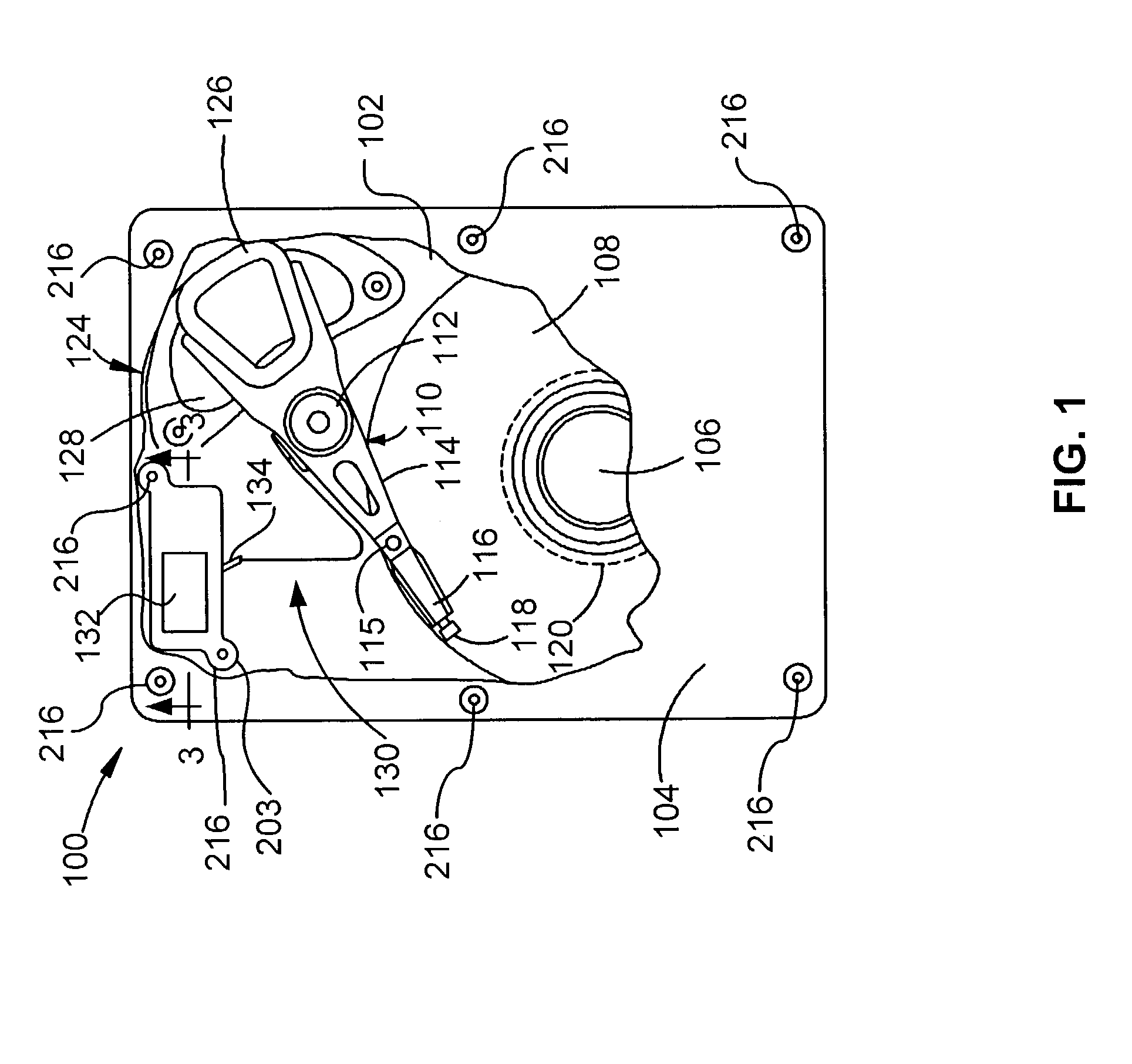
[0018]A disc drive 100 constructed in accordance with one embodiment of the present invention is shown in FIG. 1. The disc drive 100 may include a base 102 to which various components of the disc drive 100 are mounted. A top cover 104, shown partially cut away, may cooperate with the base 102 to form an internal, sealed environment for the disc drive in a conventional manner. The components typically include a spindle motor 106 which rotates one or more discs 108 at a constant high speed. Information is written to and read from tracks on the discs 108 through the use of an actuator assembly 110, which in the illustrated embodiment rotates during a seek operation about a bearing shaft assembly 112 positioned adjacent the discs 108. The actuator assembly 110 includes one or more actuator arms 114 which extend towards the discs 108, with one or more flexures 116 extending from each of the actuator arms 114. The actuator arms 114 may be individual, stacked pieces or may be formed out of...


PUM


Abstract

A head flexure assembly having a flexure with a built in microactuator is disclosed. The flexure is divided into four portions: a base plate portion for attaching the flexure to an actuator arm; a load beam portion for suspending a transducing head; a parallelogram portion connecting the load beam portion and the base plate portion and allowing for the translational movement of the load beam portion with respect to the base plate portion; and a driving frame portion. The parallelogram portion has two substantially parallel members that attach the base plate portion to the load beam portion. The parallel members limit the movement of the load beam portion relative to the base plate portion to translational movement. The driving frame portion has piezoelectric element that in response to a control signal produces a force, orthogonal to the flexure's longitudinal axis, between the base plate portion and the load beam portion.

Description

RELATED APPLICATIONS[0001]This application claims priority of U.S. provisional application Ser. No. 60 / 399,537, filed Jul. 30, 2002.FIELD OF THE INVENTION[0002]This application relates generally to data storage devices and more particularly to an actuator assembly for a data storage device.BACKGROUND OF THE INVENTION[0003]One function of a data storage device such as a disc drive is reliable storage and retrieval of information. Using one common implementation of a disc drive as an example, data is stored on one or more discs coated with a magnetizable medium. Data is written to the discs by one or more transducers, typically referred to as read / write transducers, mounted to an actuator assembly for movement of the transducers relative to the discs. The information may be stored on a plurality of concentric circular tracks on the discs until such time that the data is read from the discs by the read / write transducers. Each of the concentric tracks is typically divided into a plurali...

Claims


Application Information

Patent Timeline
IPC IPC(8): G11B5/56G11B5/55
CPCG11B5/5552
Inventor MA, JIANXU
Owner SEAGATE TECH LLC
Why Eureka
Try Eureka