Vehicle backward movement assist device and vehicle parking assist device

a technology of vehicle backward movement and assist device, which is applied in the direction of underwater vessels, special data processing applications, and non-deflectable wheel steering. it can solve the problems of difficult for a driver to set the target parking position with high precision, and many beginning drivers are not good at back-in parking or parallel parking

Active Publication Date: 2006-05-02
AISIN SEIKI KK +1
View PDF13 Cites 51 Cited by
  • Summary
  • Abstract
  • Description
  • Claims
  • Application Information

AI Technical Summary

Benefits of technology

[0008]It is preferable that the displaying means displays the image of the rear view from the vehicle and superimposes the first or second target position of the vehicle moved based upon the first or second target position and the detected moving amount on the image of the rear view from the vehicle before the first or second target parking position is set by the target parking position inputting means. Therefore, a further operation to set the target parking position continuously can be reduced.

Problems solved by technology

Especially, many beginning drivers are not good at the back-in parking or the parallel parking.
However, according to the above-described parking guiding device, which sets the target parking position with the image captured by the camera, there is a relatively long interval between the an the target parking position and a vehicle current position when the vehicle is about to back up.
In this case, the target parking position may be displayed at a relatively small scale such that it may be difficult for a driver to set the target parking position with high precision.
Therefore, even when the driver attempts to set the target parking position again, it may take time for the drive to modify the target parking position to be displayed.
The above mentioned matter that it may take time for the driver to modify the target parking position to be displayed may occur when the vehicle backs up in error during the target parking position modification.

Method used


Image

  • Vehicle backward movement assist device and vehicle parking assist device
  • Vehicle backward movement assist device and vehicle parking assist device
  • Vehicle backward movement assist device and vehicle parking assist device

Examples


Embodiment Construction

[0031]An embodiment of the present invention will be described hereinbelow in detail with reference to the accompanying drawings.

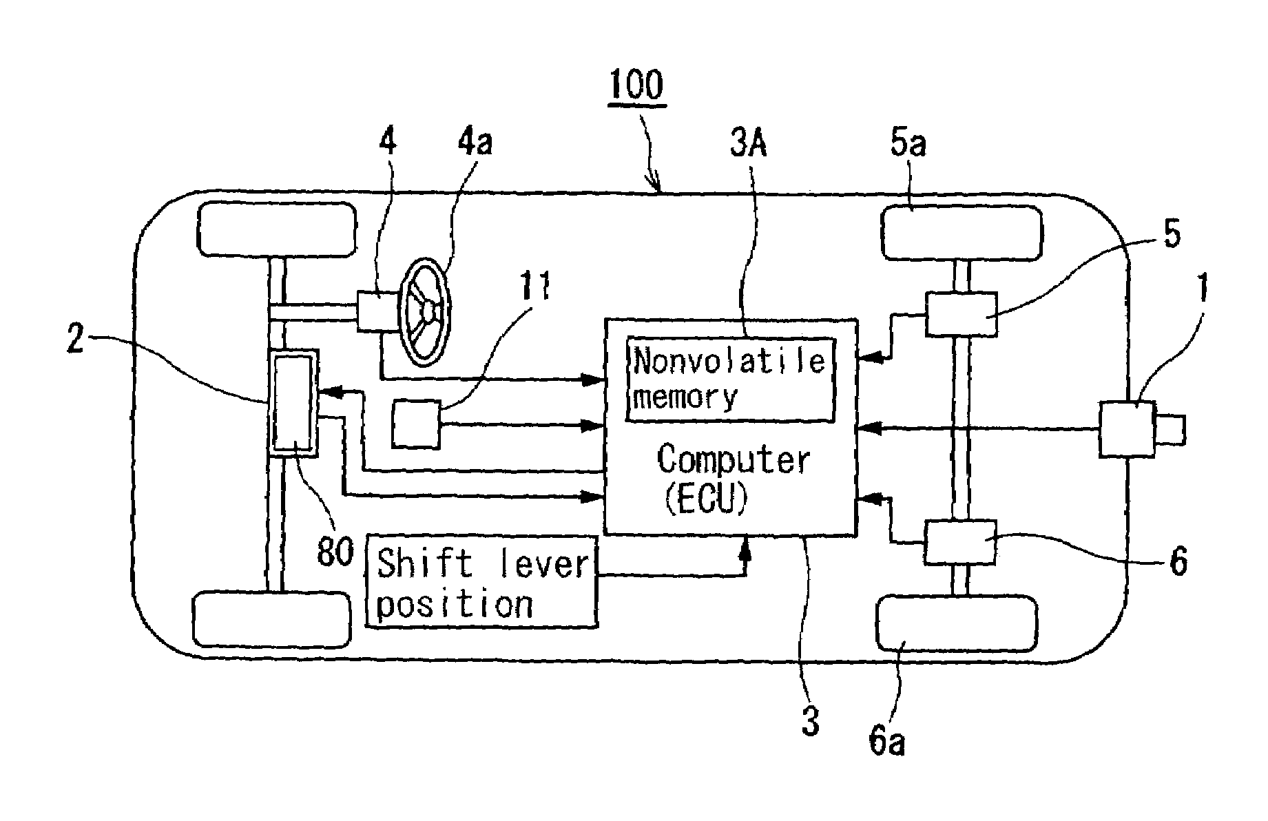
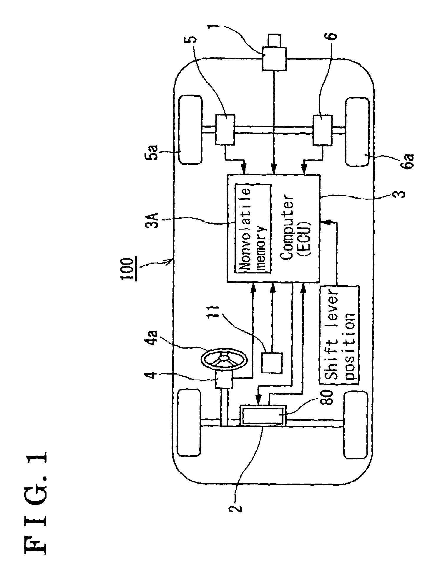
[0032]With reference to FIG. 1, a camera 1, which is fixedly mounted at a rear portion of a vehicle 100, serves as an image capturing means 60 for capturing an image of a rear view of the vehicle 100. As far as the camera 1 can capture the image of the rear view from the vehicle 100, any type of camera such as a wide angle camera, a standard angle camera, and so on as non-limiting examples can be applied. Generally, a charged coupled device (CCD) camera is employed. When the wide angle camera is applied as the camera 1, the camera is required with compensation. A display 2 directly displays the image of the rear view stereo-image-picked up by the camera 1 via a signal process. A target parking position (i.e. referred to as a target position when this embodiment is applied for a vehicle backward movement assist device) computed by a computer (ECU, a control...


PUM


Abstract

A vehicle backward movement assist device includes a vehicle path determining means for determining a path from a current position of the vehicle moved at a moving amount detected by a vehicle moving amount detecting means to a first target position or a second target position, the vehicle path determining means determining the path by repeatedly calculating the path, and a displaying means for displaying an image of a rear view from a captured by an image capturing means, the displaying means superimposing the first or second target position of the vehicle moved based upon the first or second target position and the detected moving amount on the image of the rear view from the vehicle, the second target position calculated by updating the first target position.

Description

CROSS REFERENCE TO RELATED APPLICATIONS[0001]This application is based on and claims priority under 35 U.S.C. §119 with respect to Japanese Patent Application 2003-304103, filed on Aug. 28, 2003, the entire content of which is incorporated herein by reference.FIELD OF THE INVENTION[0002]This invention generally relates to a vehicle parking assist device capable of assisting a vehicle maneuver such as a back-in parking and a parallel parking when a vehicle turns its orientation at tight and restrictive spaces such as less-traffic three-forked road and intersection. More particularly, this invention pertains to a vehicle backward movement assist device having a vehicle parking assist device capable of assisting a vehicle maneuver such as a back-in parking and a parallel parking when a vehicle turns its orientation at tight and restrictive spaces such as at less-traffic three-forked road and intersection.BACKGROUND[0003]Back-in parking or parallel parking generally require a relatively...

Claims


Application Information

Patent Timeline
Patent Type & Authority Patents(United States)
IPC IPC(8): G06F7/00B60R21/00B60R1/00B62D15/02G06T1/00H04N7/18
CPCB62D15/0285B62D15/028B60T2201/10
Inventor TANAKA, YUUIWATA, YOSHIFUMISATONAKA, HISASHIENDO, TOMOHIKOKUBOTA, YUICHIMATSUI, AKIRAIWAKIRI, HIDEYUKISUGIYAMA, TORUKAWAKAMI, SEIJIIWAZAKI, KATSUHIKOKATAOKA, HIROAKI
Owner AISIN SEIKI KK
Why Eureka
Try Eureka