System and method for providing satellite signals to multiple receiving units

a satellite signal and receiving unit technology, applied in satellite broadcast receiving, broadcast receiving circuits, television systems, etc., can solve the problems of multiple dish antennae, unsuitable signal splitters, and inconvenient installation of satellite antennas, etc., to achieve efficient and cost-effective

Inactive Publication Date: 2006-05-02
GLENN R BRYCE
View PDF3 Cites 34 Cited by
  • Summary
  • Abstract
  • Description
  • Claims
  • Application Information

AI Technical Summary

Benefits of technology

[0025]The result of the configuration of the present invention is that the switching between satellite signals, and between satellite signals and terrestrial signal is transparent to the viewer, allowing for seamless transitions.
[0026]Heretofore, it has not been known that the poling and circuitry characteristics of various DBS multi-switches would be compatible in such a way that they could be combined in the manner disclosed by the present invention. However, if DBS switches are selected in such a manner that such compatibility is achieved, such a system allows for an efficient and cost effective solution for providing multiple satellite signals to multiple receiving units.
[0027]Other embodiments consistent with the principles of the present invention include but are not limited to the following: First, the use of SW28 or SW38 switches as primary switches and SW21 switches as secondary switches allows signals from two satellites

Problems solved by technology

Signals from any single satellite may contain many channels, however, a signal from any one satellite will not contain all available broadcasts.
At high frequencies, signal splitters are undesirable due to substantial power loss.
Therefore, many of these configurations require multiple DISH antennae, or other costly equipment.
This configuration is limited to providing signals to a single receiving unit, and must be manually switched between the satellite signal and the local signal.
Adding more receiving units to t

Method used


Image

  • System and method for providing satellite signals to multiple receiving units
  • System and method for providing satellite signals to multiple receiving units
  • System and method for providing satellite signals to multiple receiving units

Examples


Embodiment Construction

[0045]While this invention is susceptible of embodiments in many different forms, there is shown in the drawings and will herein be described in detail preferred embodiments of the invention with the understanding that the present disclosure is to be considered as an exemplification of the principles of the invention and is not intended to limit the broad aspects of the invention to the embodiments illustrated.

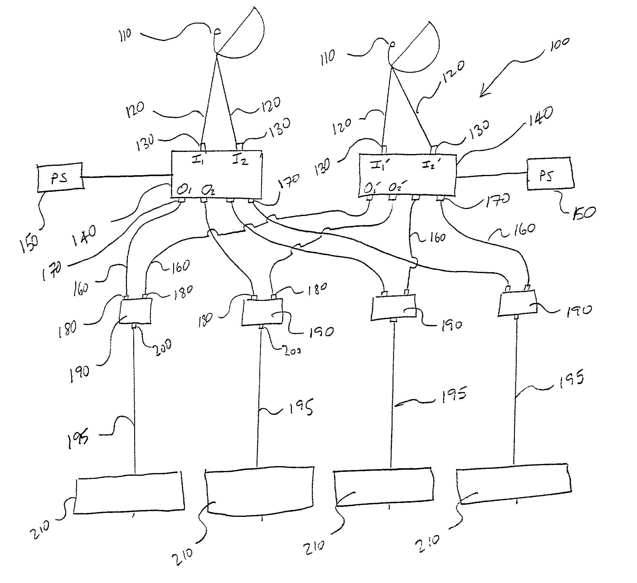
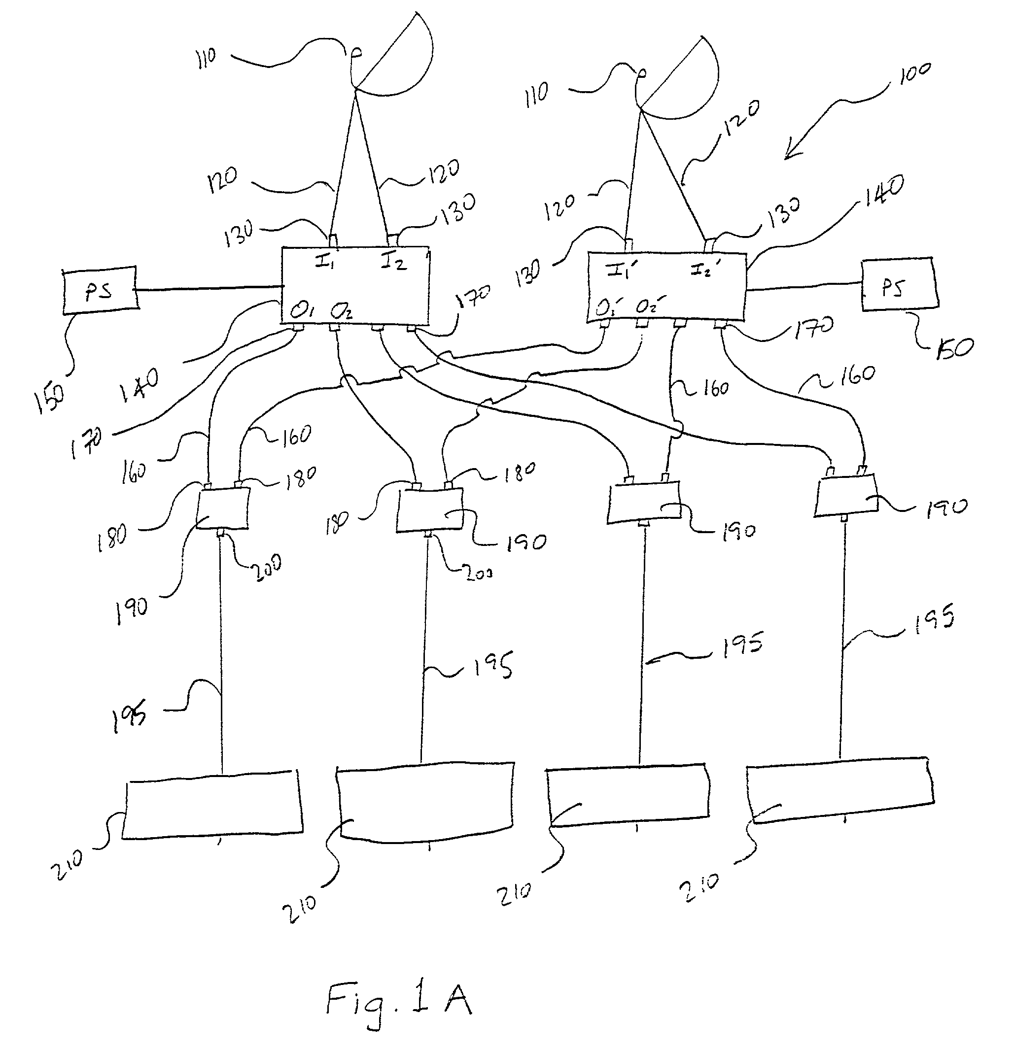
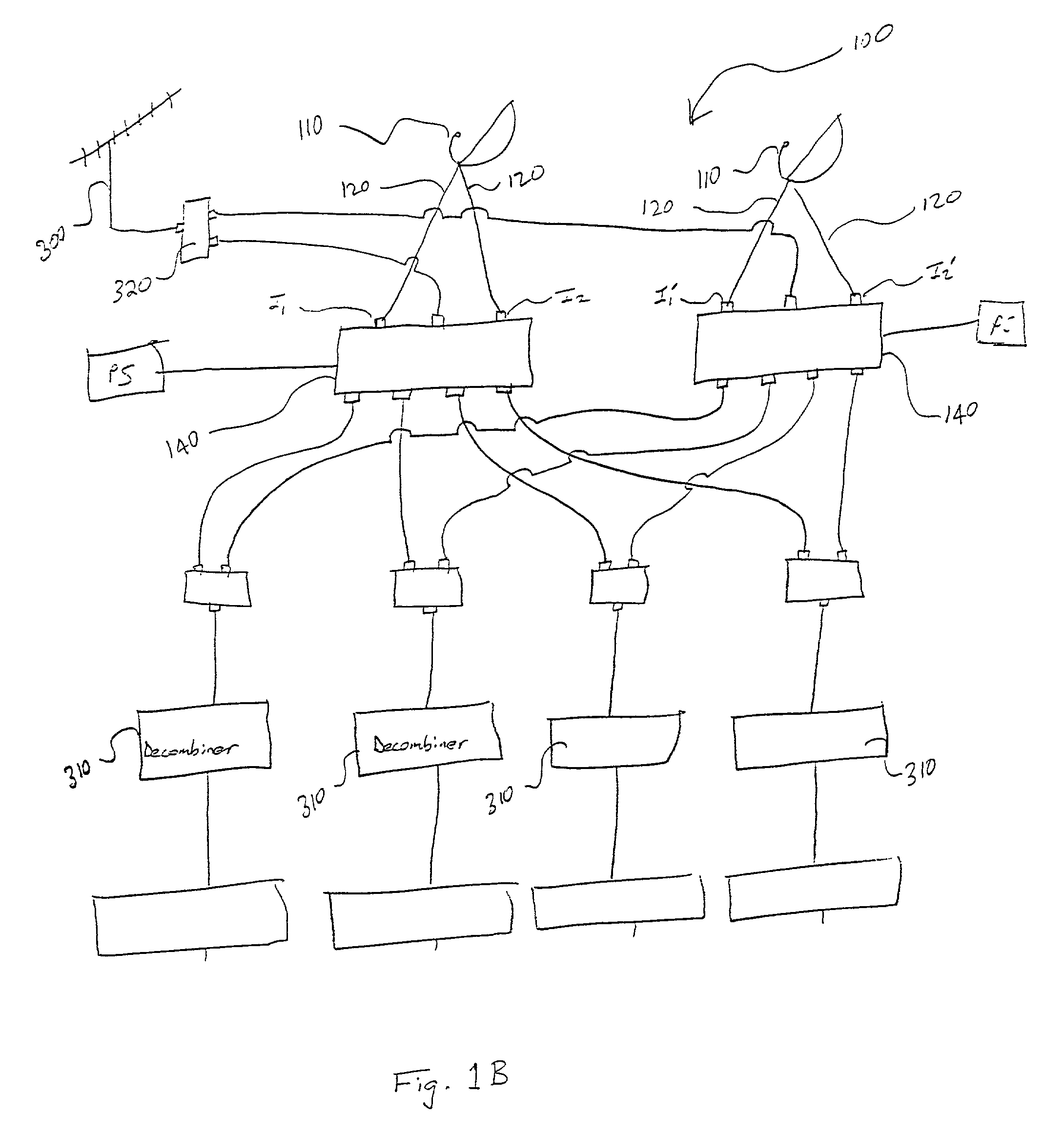
[0046]A system 100 for providing signals from a plurality of satellites to a plurality of receiving units is disclosed. First and second receptors 110 are provided for receiving first and second satellite signals, respectively. The receptors 110 are preferably Low Noise Block components (LNBs) which are placed at or near the focal point of a parabolic satellite DISH to optimize reception of a satellite signal, however, it is contemplated that any suitable receptor component capable of receiving a satellite signal could be utilized. Furthermore, it is contemplated that two sepa...


PUM


Abstract

A system and method for providing signals from a plurality of satellites to a plurality of receiving units is disclosed. The system and method of the present invention make efficient use of multi-switches to enable multiple receiving units to seamlessly alternate between channels of various satellite signals, and optionally between satellite signals and terrestrial antenna signals. In basic form, first and second receptors, such as DISH satellite LNBs, are connected to input ports of primary Digital Broadcast System multi-switches having multiple input ports and output ports. The output ports of the first such primary multi-switch are conductively connected to first input ports of at least two secondary multi-switches, and the output ports of the second such primary multi-switch are conductively connected to second input ports of the same secondary multi-switches. The outputs of the secondary multi-switches are provided to receiving units. The multi-switches are matched such that poling and circuitry components are compatible and enable the seamless alternation between channels originating from different signals.

Description

TECHNICAL FIELD[0001]The present invention relates to a system and method for providing satellite signals to multiple receiving units, and more specifically to a system and method for efficiently utilizing multi-switches to provide signals from a plurality of satellites to a plurality of receiving units such that transitions are transparent to viewers.BACKGROUND OF THE INVENTION[0002]Traditionally, satellites for transmitting numerous television channels are stationed in orbit, generally over the equator, and remain substantially stationary with respect to the Earth. Signals from any single satellite may contain many channels, however, a signal from any one satellite will not contain all available broadcasts. Commonly, signals from as many as three or four satellites may be desirable to serve a single viewer or a single building complex.[0003]Satellite signals are typically collected using a Digital Sky Highway antenna, or DISH antenna, aligned with the target satellite. DISH antenn...

Claims


Application Information

Patent Timeline
IPC IPC(8): H04N7/20
CPCH04N7/20H04H40/90
Inventor GLENN, R. BRYCE
Owner GLENN R BRYCE
Why Eureka
Try Eureka